This thread has been locked.

If you have a related question, please click the "Ask a related question" button in the top right corner. The newly created question will be automatically linked to this question.

AWR1843: Regarding specifications of radars

Part Number: AWR1843
Other Parts Discussed in Thread: IWR6843, IWR1642, ,

Hi Team,

I have AWR1843, IWR6843 & IWR1642 these radar chips with me and I am trying to evaluate these radars for my application. My application is obstacle avoidance. From these radars I am trying to figure out best suitable radar for my application. 

I am trying to verify the specs of radars with the data mentioned in documents. Like vertical fov, horizontal fov, distance etc. But the result is far different form the mentioned specs.

So just want to know about the test cases or test procedure TI has done so that same I can replicate and test it. This will be more helpful for me.

Thanks,

Manoj

  • Hi Manoj,

    Thanks for your post. Please enable us with some more details on your project. 

    1. From past E2E threads, it seems the application is obstacle avoidance for UAS/drones. could you confirm?
    2. Could you share your testing methods and results?

    Thank you,

    Jin

  • Hi Jin,

    Sure, below is my test setup, steps and result.

    Test setup:

    1. AWR1843BOOST radar.

    2. Firmware used for radar is "lab0007_medium_range_radar".

    3. Radar is powered using micro usb. 

    4. PC application used is "MRRVisualizer".

    5. Drone is used as an object.

    Steps:

    1. I placed a radar on tripod of 1m height approx. Radar is facing towards sky. 

    2. I fly drone(object) over the radar at distance 10m, 30m, 40m and 55m.

    3. Then I move drone(object) slightly left from tripod/radar position and similarly on right side to get the horizontal/azimuth FOV.

    4. I keep it moving until radar application in pc detects the drone(object) and I note down the distance.

    5. Then I move drone(object) front and back from tripod/radar position to get the vertical/elevation FOV. 

    6. I keep it moving until radar application in pc detects the drone(object) and I note down the distance.

    7. So, by knowing the distance of drone from tripod to left, tripod to right and left to right I calculated horizontal/azimuth FOV using triangle formula. Here is the link of triangle calculator Triangle Calculator.

    8. Similarly, calculated vertical/elevation FOV using this triangle calculator.

    Please find the below results,

    From tripod to left distance of drone(km) From tripod to right distance of drone(km) From Left to right distance of drone(km) FOV(degrees) Distance of drone vertically from tripod(meters)
    0.01 0.0105 0.0204 168.673(Horizontal/Azimuth) 10m
    0.0166 0.0164 0.0325 160.027(Horizontal/Azimuth) 30m
    0.0134 0.0164 0.0297 170.562(Horizontal/Azimuth) 40m
    0.0126 0.007 0.0195 167.914(Horizontal/Azimuth) 55m
    From tripod to back distance of drone(km) From tripod to front distance of drone(km) From back to front distance of drone(km) FOV(degrees) Distance of drone vertically from tripod(meters)
    0.0032 0.0039 0.0062 121.361(Vertical/elevation) 10m
    0.0054 0.0085 0.0134 148.354(vertical/elevation) 30m
    0.0067 0.0085 0.0148 153.463(vertical/elevation) 40m

    Please let me know if you need any further details.

    Thanks,
    Manoj

  • Hi Manoj,

    Thank you for the details. We have not done any testing for detection of drones - could you clarify which TI-provided specs you are comparing your results against?

    FoV is defined by the physical antenna array. For more information on this, please refer to this similar thread: https://e2e.ti.com/support/sensors-group/sensors/f/sensors-forum/1093172/iwr1843boost-awr1843-medium-range-radar-demo

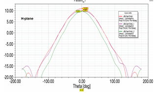
    The FoV, as provided in the EVM user's guide can be determined from antenna radiation patterns (Fig 11-12). These patterns are derived from testing the EVM in an anechoic chamber using corner reflectors.

    Thank you,

    Jin

  • Hi Jin,

    The document which I was talking about is thread which I have gone through earlier, my bad I used word document. 

    I have referred this thread earlier, https://e2e.ti.com/support/sensors-group/sensors/f/sensors-forum/955732/awr1843boost-max-field-of-view

    And the thread which you have shared in previous message having another thread in it also mentioned the same FOV. If I compare my results with those references so my results have many differences.

    Thanks,
    Manoj

  • Hi Manoj,

    Thank you for the clarification. The FoV provided in the threads is based on threshold values from the radiation patterns. For example, +-50 degrees horizonal FoV is based on a 6dB drop in gain compared to at 0 degrees. We limit the FoV provided based on these thresholds since objects at large angles will have lower signal strength (SNR) and may not be detected.

    It is possible that the drone used in your testing may be highly reflective, enabling higher SNR and detection at larger FoVs than provided.

    Without considering signal strength, the FoV limit of the angle estimation technique alone is +=90 degrees for the antenna geometry of the board. Please refer to this thread: https://e2e.ti.com/support/sensors-group/sensors/f/sensors-forum/988784/awr1843-awr1843-fov-for-mrr-srr-and-ussr

    Thank you,

    Jin

  • Hi Jin,

    Your input is really helpful. 

    So, from your explanation what I have understood is getting FOV more than what it is mentioned in those threads is possible. Depends on your object how reflective it is. And as per the antenna geometry maximum limit would be +-90 degrees (total 180 degrees) FOV. So, getting FOV up to 150 degrees or 160 degrees in my case is possible because may be my drone as an object is that highly reflective. 

    Let me know if my understanding is correct.

    Thanks,
    Manoj

  • Hi Manoj,

    Yes, your understanding is correct.

    Thank you,

    Jin

  • Thank you, Jin.