This thread has been locked.
If you have a related question, please click the "Ask a related question" button in the top right corner. The newly created question will be automatically linked to this question.
Greetings,
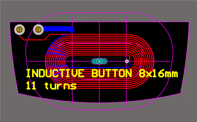
We are in the process of integrating a custom coil design based on the LDC2112 sensor IC. We have recently purchased a LDC2114EVM development board along with reference coil designs. The reference coils seem to work out of the box with the default configurations of the Sensing Solutions EVM GUI tool, but using a custom coil seems to give no results. The custom coil (referenced in the image below) has the following parameters: Flex PCB, thickness 0.11mm, coil dimensions 8x16mm (racetrack), trace width 6mil, space between traces 5mil, 2 layers, 11 turns, 0.333 oz. copper. Could someone please guide me through the parameter configuration of the sensor IC (and possible HW changes i.e. changing the Ccom capacitor value on the LDC2114EVM) so that we can get some usable and detectable results from the coil?
Thank you very much,
Yours sincerely,
Stefan
Stefan,
Just so you know, many of our customers have struggled getting to production with the FDC2x1y family because of EMC.
If you can consider an alternative, please consider the FDC1004, a capacitive sensor which does not use a resonant LC tank as an input.
If you would like to know more about the FDC1004, please see the E2E FDC1004 Frequently Asked Questions page.
That being said, please confirm the expected inductance of your coil thru measurement or simulation and be sure the resonating cap on the EVM will result in the sensor frequency that falls within the 1kHz to 10MHz range.
If you already gone thru those steps, please update this thread and we will proceed to next steps.
Regards,
John
Hi John, thank you for your quick response! In your reply, you have referenced "the FDC2x1y family". This is a capacitive sensor series (capacitance to digital converter), did you mean to reference the LDC family of sensors (which are the inductive sensing ICs)?
Stefan,
Apologies for that poor reply.
You are, of course, correct. Please ignore that first paragraph in my previous reply. Not sure what I was thinking there.
More to the point, please confirm the inductance value of your flex coil, and that with the on-board capacitance, it will resonate at a frequency within the published limit of the LDC2114 (1MHz to 30MHz).
Regards,
John
No worries, just wanted to clear things up. I would like to measure and send you the information you want about the coil, but could you guide me through what (or how) I should acquire these measurements since I do not want to accidentally damage the input channels of the LDC2114. Do you want me to get the coil inductance at a frequency (within 1-30MHz) with certain capacitor values also added to the coil (the LDC2114EVM board comes with I think 47pF caps attached between every COM and INx channel, although this will probably require changing)?
Stefan,
The best approach would be to measure the coil by itself - w/o a target or any other circuitry attached, over a frequency range that encompasses your frequencies of interest. If you don't have a preferred frequency then take some points over the 1Mhz-30MHz range.
You should be able to do the measurements with an LCR meter or a network analyzer.
The intent is to find coil's inductance versus frequency and make sure your frequencies of operation are ~20% less than the coil's self-resonant frequency.
Above the self-resonant frequency the coil looks capacitive rather than inductive, so it won't support sensor oscillation.
For more info on this topic, please see the app notes:
Regards,
John
Hi John,
I have measure the coils inductance, it is 5.7uH at 1MHz. The self resonance occurs at about 13MHz. Adding a parallel cap of 150pF moves the resonance to around 5MHz. When the capacitor is added, and a series 1KOhm resistor, the |Rp| is measured and shown in the graph below:
This is measure with no target nearby. The maximum RP is 7Kohm at ~8.5Mhz.
Stefan,
Thanks for the information.
The next step should be looking at the LDC input signal.
With the coil (w/o target) connected to the configured and active LDC, what does the coil waveform look like in terms of frequency, DC offset and peak-to-peak amplitude?
BTW, our IT security policy would not let me access the graph you posted. If you are not comfortable positing images to this forum, please let me know and we can arrange another option.
Regards,
John
Regards,
John
John,
It would be great if I could get in touch with you over e-mail so we can exchange pictures in higher quality regarding LDC measurements.
Hi John,
While performing the measurements, at one point the INx channels stopped exciting oscillations in the coil and just look like square waves. Can you please help me resolve why this is and why the LDCTOUCHCOMCOILEVM no longer work with the board either? Looking at the status register, it seems that LC_WD is sometimes triggered to '1'.
Stefan,
I have sent you an E2E friend request.
Please accept it and we can exchange private messages, files, etc.
If you have changed the sense coil, you may have to change the resonant cap as well.
If that isn't done, the resonant frequency may fall outside the device's supported range.
Regards,
John
Thank you Stefan.
We can close this thread and continue the discussion via the E2E messaging channel, or we can keep can keep working via this thread and use the messaging channel to exchange files.
Please let me know your preference and we can move forward.
Regards,
John
Stefan,
I am closing this thread since we have moved the conversation to private messaging.
John