This thread has been locked.

If you have a related question, please click the "Ask a related question" button in the top right corner. The newly created question will be automatically linked to this question.

FDC2114EVM: Information about impact of wire connection between microcontroller and FDC 2114

Part Number: FDC2114EVM
Other Parts Discussed in Thread: FDC2114

Hi group members
I have two questions
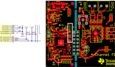
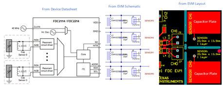
I have connected my FDC 2114 EVM with another outsider  microcontroller and bypass the MSP430 microcontroller . I have been transferring the data from FDC 2114 to outsider microcontroller through some wires.
 1) Does there is need of pullup resistor between the data wires  SCL AND SDA and external microcontroller
2)  Does the internal capacitance of external wires that i used to transfer data  from FDC 2114 EVM to outsider microcontroller also add in the total capacitance that will shown by the  external microcontroller or not.

Actually i have experiment with different capacitance value wires for data transfer , but every time the default value shown by external microcontroller (STM) is same irrespective of whatever the internal capacitance of that wirer i used
Kindly sort out this issue
Thanks in advance

  • Hello Hafiz,

    Thank you for considering to use Texas Instruments.

    1. Depending on whether you snapped off the left side of the board or simply desoldered the MSP430, you may or may not need the pullup resistors. In the snippits below you can see that we do have pull up resistors near the MSP430 on the schematic. And on the board layout we see that those are in the white box on the left side of the evm with the microncontroller which can be potentially snap (severed) from the FDC2114.
    2. Im not sure I follow your question. Capacitance for the wires between the FDC2114 and the microcontroller will affect the rise and fall times of your i2c signals and I think the choice of pull-up resistors should dominate. As for the capacitance you are using for sensing purposes that should not be affected.  That capacitance is part of the LC tank shown in the snippits below.

    For future reference most TI EVM user guide’s will have the schematic and board layout near the end of the user guide under.  You can quickly navigate there through the table of contents if the user guide appears to be long.