Other Parts Discussed in Thread: DRV5011
Hello Team,
We are using 3 qty DRV5012AEDMRT hall sensor in our flat BLDC motor for commutation purpose. There are placed 120 degree apart. Motor is of 16 pole magnet (8 pole pair).
distance between hall sensor surface and magnet is 1.6mm
when we drive motor using sensored driver we observed it is taking very high current and when we driver same motor with sensorless driver it consume very less current.
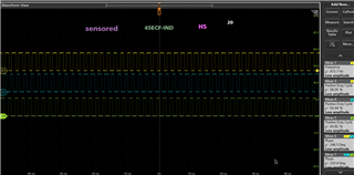
With sensored driver we observed hall sensor waveform on oscilloscope and found that at low speed , the duty cycle and phase shift is with in spec i.e 50% and 120 degree respectively.
As we increases speed the duty varies and phase shift also.
for reference refer below snapshot of hall sensor at different speed. Can you please help us to understand what will be root cause for this and how can we improve duty cycle at higher speed.
1. speed -1300 rpm
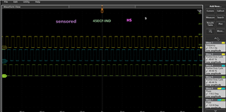
2. speed -5300 rpm