Other Parts Discussed in Thread: TMAG5170, , TMAG5170-CODE-EXAMPLE
Hi all,
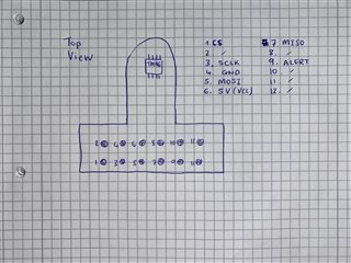
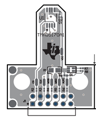
I'm currently trying to work with the Hall-Effect Sensor TMAG5170.TMAG5170UEVM
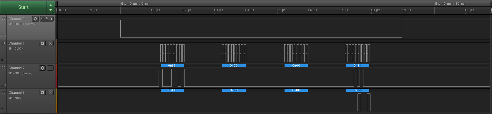
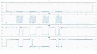
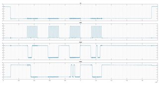
It uses SPI protocol to communicate with microcontrollers. I am using the Arduino IDE 2.3.0 and an Arduino Uno to try control the sensor and I am having much difficulty writing into the registers of the TMAG5170. It seems I am able to read the registers but I cannot write in them. I am quite certain my pins are all correctly connected, I have VCC=5V. I previously tried VCC=3.3V as well. I am unsure where to connect the ALARM pin, I assumed any GPIO pin can work, but in this project I don't even use the alarm feature. I am trying to use code given by TI Example Code by TI 1 . I have then tried to use code I found on GithubGithub Project 2 . It is essentially the same stuff as the TI example code. Using both examples (code from TI and from Github) I could read the registers but not write in them. I am really stumped, so here is my code so far and hopefully someone has time and expertise to see where I am going wrong:
#include "SPI.h"
#include "tmag5170.h"
#include "hal.h"

// Global Variables
static uint16_t SYSTEM_CONFIG_stored = 0;
#define DATA_TYPE_RESULTS    ((SYSTEM_CONFIG_stored & ~(SYSTEM_CONFIG_DATA_TYPE_MASK)) >> 6)

// Pin definitions
const int CSpin = 10;

void setup() {
  // put your setup code here, to run once:
  pinMode(CSpin, OUTPUT);

  digitalWrite(CSpin, HIGH); // Deselect the TMAG5170 initially
  // SPI.beginTransaction(SPISettings(100000, MSBFIRST, SPI_MODE0));
  SPI.begin();

  Serial.begin(9600);

  // Configure device:
  TMAG5170startup();
  // Configuration Mode
  enterConfigurationMode();
  // Enable/disable functionalities and measurements
  enableMagChannels(MAG_CH_EN_BITS_XYZ);
  enableTemperatureMeasurement();
  // Sample Rate
  setSampleRate(CONV_AVG_BITS_16X);
  // Set ranges magnetic measurement
  setRanges(SENSOR_CONFIG_X_RANGE_50mT, SENSOR_CONFIG_Y_RANGE_50mT, SENSOR_CONFIG_Z_RANGE_50mT);

  delay(100);
}

void loop() {
  // put your main code here, to run repeatedly:

  // // Example magnetic sensor temperature read
  // float magTemperature = getMeasurementNrmlTEMP();

  // // Print magnetic sensor temperature readout
  // Serial.print("Magnetic Sensor Temperature: ");
  // Serial.print(magTemperature);
  // Serial.println(" °C");

  // // Example magnetic readout
  // float magX = getMeasurementNrmlX();

  // // Print magnetic readout
  // Serial.print("Magnetic Flux X-component: ");
  // Serial.print(magX);
  // Serial.println(" mT");

  // Some checks
  int response = normalReadRegister(X_THRX_CONFIG_ADDRESS);
  Serial.print("X_THRX_CONFIG_ADDRESS: ");
  Serial.print("Data: 0x");
  Serial.println(response, HEX);

  int response1 = normalReadRegister(SENSOR_CONFIG_ADDRESS);
  Serial.print("SENSOR_CONFIG_ADDRESS: ");
  Serial.print("Data: 0x");
  Serial.println(response1, HEX);

  delay(1000);  // Adjust the delay based on your desired reading frequency
}


//****************************************************************************
//****************************************************************************
//
// Note (Matis)
//
// These functions are to 'initiate/connect/communicate' with the hardware.
// They are taken from the TI example code (hal_ex.c) and edited to work in
// this environment
//
//****************************************************************************
//****************************************************************************

void spiSendReceiveArrays(const uint8_t dataTx[], uint8_t dataRx[], const uint8_t byteLength)
{

    // Require that dataTx and dataRx are not NULL pointers
    assert(dataTx && dataRx);

    // Set the nCS pin LOW
    digitalWrite(CSpin, LOW);

    // Send all dataTx[] bytes on MOSI, and capture all MISO bytes in dataRx[]
    int i;
    for (i = 0; i < byteLength; i++)
    {
        dataRx[i] = spiSendReceiveByte(dataTx[i]);
    }

    // Set the nCS pin HIGH
    digitalWrite(CSpin, HIGH);
}

uint8_t spiSendReceiveByte(const uint8_t dataTx)
{
    // Remove any residual or old data from the receive FIFO
    // Could come later; something along the lines of making sure dataRx[] is empty

    // SSI TX & RX
    uint8_t dataRx;
    dataRx = SPI.transfer(dataTx);

    // TODO: can we remove the SSIDataGetNonBlocking() call here and move it to spiSendReceiveArrays()?
    // TODO: Add error checking and handling here in case of TX or RX problems...

    return dataRx;
}

//****************************************************************************
//****************************************************************************
//
// Note (Matis)
//
// From now on this are functions given in the TI example code (tamg5170_ex.c)
//
//****************************************************************************
//****************************************************************************

//****************************************************************************
//! Initialization function
//!
//! This function MUST be ran at the beginning of any implementation using this
//! example code. This is needed because the SYSTEM_CONFIG register is needed to
//! be tracked and updated accordingly to prevent losing track of the DATA_TYPE
//! in use by the device.
//!
//! If CRC is being disabled per the header definition being enabled, then this
//! function also sends the command to disable CRC on the device as well.
//! NOTE: if CRC is being disabled then the RESET_DEVICE_IN_STARTUP should be
//! enabled as well
//****************************************************************************
void TMAG5170startup()
{
    // (OPTIONAL) Provide additional delay time for power supply settling
    delayMicroseconds(50);

#ifdef RESET_DEVICE_IN_STARTUP
    // SYSTEM_CONFIG_stored will be set to default in this function
    resetDevice();
#else
    // The default implementation of this initialize function is resetting only
    // the SYSTEM_CONFIG register and leaving the other registers unchanged.
    writeToRegister( SYSTEM_CONFIG_ADDRESS, SYSTEM_CONFIG_DEFAULT );
    SYSTEM_CONFIG_stored = SYSTEM_CONFIG_DEFAULT;
#endif

#ifdef DISABLE_CRC_IN_STARTUP
    // Sends command to disable CRC verfication and calculation on device-side
    // MUST be called first in implementation for commands from other functions
    // to be accepted when DISABLE_CRC_IN_STARTUP is used.
    uint8_t dataTx[4] = {0x0F,0x00,0x04,0x07};
    uint8_t dataRx[4] = {0};
    sendAndReceiveFrame(dataTx,dataRx);
#endif
}

//****************************************************************************
//! Reset Device to Factory Settings
//!
//! This function uses the DeepSleep functions to reset the device's registers back to the
//! default settings outlined in the datasheet. This function also resets the
//! SYSTEM_CONFIG_stored variable to the default value in the enterDeepSleepMode function.
//****************************************************************************
void resetDevice()
{
    enterDeepSleepMode(); // Deep Sleep Mode resets the device to its default settings
    exitDeepSleepMode();
}

//****************************************************************************
//! Enter Deep Sleep Mode
//!
//! Make sure to use the exitDeepSleepMode function to properly exit Deep Sleep Mode.
//! Deep Sleep Mode can be alternately exited with a short pulse on the CS pin.
//!
//! WILL WORK IN SPECIAL READ MODE, DEEP SLEEP MODE RESETS DEVICE TO FACTORY SETTINGS
//! (EXITS SPECIAL READ MODE)
//****************************************************************************
void enterDeepSleepMode()
{
    // Send Write command, Deep Sleep resets device to factory settings so
    // an initial register read is not needed (DEVICE_CONFIG default is 0x0000)
    writeToRegister( DEVICE_CONFIG_ADDRESS, DEVICE_CONFIG_OPERATING_MODE_DeepSleepMode );
    SYSTEM_CONFIG_stored = SYSTEM_CONFIG_DEFAULT;
    delayMicroseconds(100);
}
//****************************************************************************
//! Exit Deep Sleep Mode
//! (Use this function instead of a different operation mode change function to
//! exit Deep Sleep mode properly)
//!
//! Exits Deep Sleep Mode by pulsing LOW on the CS pin and waiting for the chip
//! to start up. (t_start_deep_sleep)
//!
//! DOES NOT WORK IN SPECIAL READ MODE [DATA_TYPE field at 0x028-6 does not equal 000b]
//****************************************************************************
void exitDeepSleepMode()
{
    // A LOW pulse is needed on CS to exit Deep Sleep Mode (enters Configuration Mode)
    csPulse();

#ifdef  MAX_DELAYS_IN_OPMODE_CHANGES
    delayMicroseconds(500); // max expected delay as given by t_start_deep_sleep (datasheet pg. 10)
#else
    delayMicroseconds(260); // typical delay for t_start_deep_sleep at Vcc = 2.3V (datasheet pg. 10)
#endif
}

//****************************************************************************
//****************************************************************************
//
// SPI fucntions
//
//****************************************************************************
//****************************************************************************

//****************************************************************************
//! Send and Receive Frame
//!
//! Takes in the frame to transmit by SPI and the array to put the received frame in
//!
//! dataTx[4] - unint8_t array of length 4 containing the bytes frame to transmit
//!             ordered with CRC-containing byte last
//! dataRx[4] - unint8_t array of length 4 of zeroes on input, will have the received
//!             frame bytes assigned to it ordered with CRC bits last
//****************************************************************************
void sendAndReceiveFrame(uint8_t dataTx[], uint8_t dataRx[])
{

#ifdef DISABLE_CRC_IN_STARTUP
    // When CRC is disabled upon system initialization, the need to calculate
    // the dataTx CRC for the TMAG5170 to accept commands is gone at the risk
    // of transmission errors being passed through.

    spiSendReceiveArrays(dataTx, dataRx, TMAG5170_FRAME_NUM_BYTES);

    // Check if SYSTEM_CONFIG was written to and update SYSTEM_CONFIG_stored if so
    if ( dataTx[0] == SYSTEM_CONFIG_ADDRESS ) SYSTEM_CONFIG_stored = (dataTx[1] << 8) | dataTx[2];
    SYSTEM_CONFIG_stored &= ~(0xC818); // Reserved bits cannot be 1, this ensures the
                                       // stored variable doesn't have them changed
#else
    // When CRC is enabled (it is by default), the CRC must be calculated and
    // included in dataTx for the TMAG5170 to accept commands.

    uint8_t crc = calculateCRC( dataTx );
    dataTx[3] = dataTx[3] | crc;

    spiSendReceiveArrays(dataTx, dataRx, TMAG5170_FRAME_NUM_BYTES);

    // The TMAG5170 also calculates the CRC for the frame it sends back to its
    // MCU. The TMAG5170 will purposely return a bad CRC if it received a
    // transmitted command with a bad CRC as well. Verifying the CRC of dataRx
    // helps confirm if dataTx was received successfully and if dataRx is valid.
    if (verifyCRC(dataRx) == 0)
    {
        // Without GLOBAL_CRC_ERROR_VAR_ENABLED defined or another error response
        // implemented, this function will not give any indication that the
        // received data has an error

        #ifdef  SEND_RECIEVE_REDUNDANCY_ENABLED

        for ( i = 0; i<4; i++ ) { dataRx[i] = 0 };
        spiSendReceiveArrays(dataTx, dataRx, TMAG5170_FRAME_NUM_BYTES);
        if ( verifyCRC(dataRx) )
        {
            // Check if SYSTEM_CONFIG was written to and update SYSTEM_CONFIG_stored if so
            if ( dataTx[0] == SYSTEM_CONFIG_ADDRESS ) SYSTEM_CONFIG_stored = (dataTx[1] << 8) | dataTx[2];
            SYSTEM_CONFIG_stored &= ~(0xC818); // Reserved bits cannot be 1, this ensures the
                                               // stored variable doesn't have them changed
            return;
        }

        #endif

        #ifdef  GLOBAL_CRC_ERROR_VAR_ENABLED
        crc_error_occurence = 1; // If redundancy is enabled too, the error bit
                                 // only flips if both sent TXs receive bad CRCs
        #endif

        return; // If a received data CRC error is detected, SYSTEM_CONFIG_stored
                // will not be updated under the assumption that whatever command
                // sent was not accepted.
    }

    // Check if SYSTEM_CONFIG was written to and update SYSTEM_CONFIG_stored if so
    if ( dataTx[0] == SYSTEM_CONFIG_ADDRESS ) SYSTEM_CONFIG_stored = (dataTx[1] << 8) | dataTx[2];
    SYSTEM_CONFIG_stored &= ~(0xC818); // Reserved bits cannot be 1, this ensures the
                                       // stored variable doesn't have them changed
#endif
}

//****************************************************************************
//! Write to Register Function (no CMD sent or value returned)
//!
//! Takes in the address of the register to edit and the 16-bit frame to overwrite it with and writes
//! the input frame to the register.
//!
//! This function replaces the whole register with the input data, make sure the values desired to be
//! unchanged are in the input data_to_write!
//!
//! This function will work in Normal and Special Read Mode.
//!
//! address       - uint8_t value from 0x00 to 0x14 containing the register address to write over
//! data_to_write - the 16-bit frame to be written to the register at address.
//****************************************************************************
void writeToRegister(uint8_t address, uint16_t data_to_write)
{
    // Check that the input address is in range
    assert(address < NUM_REGISTERS);

    // Build TX and RX byte arrays
    uint8_t dataTx[4] = { 0 };
    uint8_t dataRx[4] = { 0 };

    // MSB is 0 for WRITE command
    dataTx[0] = (address);
    dataTx[1] = (data_to_write >> 8);
    dataTx[2] = (data_to_write);
    dataTx[3] = 0x00;

    sendAndReceiveFrame(dataTx, dataRx);
}

//****************************************************************************
//! Full Read Function for Normal Data Mode (DATA_TYPE = 000b)
//!
//! Takes in an output array of length 2, address to read from, and CMD bits to send along,
//! then creates the dataTx array and calls the sendAndReturnFrame function, interpreting
//! dataRx and putting the read register in output[0] and status bits in output[1]
//!
//! output[2] - empty uint16_t array of length 2, output[0] will be assigned the returned register
//!             at the given address, output[1] will be assigned the returned status bits.
//! address   - uint8_t value from 0x00 to 0x14 containing the register address to read from
//! cmd_bits  - uint8_t value from 0x00 to 0x03 containing the CMD0 and CMD1 bits that will be sent
//!             in dataTx. LSB is CMD0, next bit is CMD1. (see header file or datasheet pg. 29 for CMD functions)
//****************************************************************************
void normalRead( uint16_t output[], uint8_t address, uint8_t cmd_bits )
{
    // Check that the input address is in range
    assert(address < NUM_REGISTERS);

    // Build TX and RX byte arrays
    uint8_t dataTx[4] = { 0 };
    uint8_t dataRx[4] = { 0 };

    // MSB is 1 for READ command
    dataTx[0] = (address | 0x80);
    dataTx[1] = 0x00;
    dataTx[2] = 0x00;
    dataTx[3] = cmd_bits << 4;

    sendAndReceiveFrame(dataTx, dataRx);
    output[0] = (dataRx[1] << 8) | dataRx[2];
    output[1] = (dataRx[0] << 4) | (dataRx[3] >> 4);
}

//****************************************************************************
//! Register-only Read Function for Normal Data Mode (DATA_TYPE = 000b)
//!
//! Takes in address to read from and returns register at address without the status bits or
//! triggering any CMD function (cmd_bits = 0x00).
//!
//! address   - uint8_t value from 0x00 to 0x14 containing the register address to read from
//****************************************************************************
uint16_t normalReadRegister( uint8_t address )
{
    uint16_t output[2] = { 0 };
    normalRead( output, address, 0x00 );
    return output[0];
}

// Note (Matis): I have excluded all Special Read Mode capabilities

//****************************************************************************
//****************************************************************************
//
// Change Device Operation Mode
//
// Note (Matis): other modes available in TI example code are Stand-by, Active Measure, Active Trigger, Sleep, Wake and Sleep, Deep Sleep
// Exit Sleep, Exit Wake Up and Sleep, Exit Deep Sleep Modes
//
//****************************************************************************
//****************************************************************************

//****************************************************************************
//! Enter Configuration Mode
//!
//! DOES NOT WORK IN SPECIAL READ MODE [DATA_TYPE field at 0x028-6 does not equal 000b]
//****************************************************************************
void enterConfigurationMode()
{
    // To prevent undefined behavior, this function does not perform its operation
    // when the DATA_TYPE field (address: 0x028-6) is not set to Normal Read Mode (000b)
    if ( DATA_TYPE_RESULTS != DATA_TYPE_RESULTS_NormalMode ) return;

    uint16_t input;
    // Set OPERATING_MODE (address: 0x006-4) to Configuration Mode (0h)
    input = normalReadRegister(DEVICE_CONFIG_ADDRESS);
    input = ( input & ~(DEVICE_CONFIG_OPERATING_MODE_MASK) ) | DEVICE_CONFIG_OPERATING_MODE_ConfigurationMode;
    writeToRegister( DEVICE_CONFIG_ADDRESS, input );

#ifdef  MAX_DELAYS_IN_OPMODE_CHANGES
    delayMicroseconds(50); // max expected delay as given by t_start_sleep (datasheet pg. 10)
#endif
}

//****************************************************************************
//****************************************************************************
//
// Notes (Matis)
//
// Functionalities omitted:
// Functions to Configure Trigger Settings
// Threshold Detection + ALERT output Settings
//
//****************************************************************************
//****************************************************************************


//****************************************************************************
//****************************************************************************
//
// Measurement Configuration Functions
//
//****************************************************************************
//****************************************************************************

//****************************************************************************
//! Enable Magnetic Axes for Measurement (also can turn all channels off)
//!
//! Takes in a 4-bit value for the MAG_CH_EN field (0x019-6)
//! mag_ch_en_bits must not be greater than 0x0F
//!
//! When mag_ch_en_bits < 0x08 its three LSBs act as a three bit enable/disable command for ZYX
//! (examples:  0x05 (0101b) => ZX enabled  |  0x02 (0010b) => Y enabled)
//!
//! When mag_ch_en_bits >= 0x08 it configures alternative sampling orders along with enabling
//! specific channels (see chart below)
//!
//!                          | enabled channels ||                  | enabled channels
//!          mag_ch_en_bits  | + sampling order ||  mag_ch_en_bits  | + sampling order
//!         _________________|__________________||__________________|__________________
//!               0x00               none       ||       0x08               XYX
//!               0x01                X         ||       0x09               YXY
//!               0x02                Y         ||       0x0A               YZY
//!               0x03               XY         ||       0x0B               ZYZ
//!               0x04                Z         ||       0x0C               ZXZ
//!               0x05               ZX         ||       0x0D               XZX
//!               0x06               YZ         ||       0x0E              XYZYX
//!               0x07               XYZ        ||       0x0F              XYZZYX
//!
//! Definitions for descriptive inputs to this function are provided in the header file.
//!
//! DOES NOT WORK IN SPECIAL READ MODE [DATA_TYPE field at 0x028-6 does not equal 000b]
//****************************************************************************
void enableMagChannels( uint8_t mag_ch_en_bits )
{
    // To prevent undefined behavior, this function does not perform its operation
    // when the DATA_TYPE field (0x028-6) is not set to Normal Read Mode (000b)
    if ( DATA_TYPE_RESULTS != DATA_TYPE_RESULTS_NormalMode ) return;

    // Check that inputs are valid
    if ( !( mag_ch_en_bits <= 0x0F ) ) return;

    uint16_t input;
    // Set MAG_CH_EN (0x019-6) to mag_ch_en_bits
    input = normalReadRegister(SENSOR_CONFIG_ADDRESS);
    input = ( input & ~(SENSOR_CONFIG_MAG_CH_EN_MASK) ) | (mag_ch_en_bits << 6);
    writeToRegister( SENSOR_CONFIG_ADDRESS, input );
}

//****************************************************************************
//! Enable Angle Measurement (also can turn off angle measurement)
//!
//! Takes in a 2-bit value for the ANGLE_EN field (0x01F-E) to determine which two
//! axes to measure the angle off of for the on-board CORDIC function in the device.
//!
//! Based on the ANGLE_EN setting, the angle will be calculated using the first axis
//! as the "horizontal" axis (positive side of axis is 0 degrees) and the second as
//! the "vertical" axis (positive side of axis is 90degrees)
//!
//! angle_en_bits can be set to 0x00 to 0x03 to configure these settings for ANGLE_EN:
//!              ANGLE_EN value | horizontal axis | vertical axis
//!                   0x00              none            none  --  (angle measurement disabled)
//!                   0x01               X               Y
//!                   0x02               Y               Z
//!                   0x03               X               Z
//****************************************************************************
void enableAngleMeasurement( uint8_t angle_en_bits )
{
    // To prevent undefined behavior, this function does not perform its operation
    // when the DATA_TYPE field (0x028-6) is not set to Normal Read Mode (000b)
    if ( DATA_TYPE_RESULTS != DATA_TYPE_RESULTS_NormalMode ) return;

    // Check that inputs are valid
    if ( !( angle_en_bits <= 0x03 ) ) return;

    // To prevent undefined behavior, this function does not perform its operation
    // when the DATA_TYPE field (0x028-6) is not set to Normal Read Mode (000b)
    if ( DATA_TYPE_RESULTS != DATA_TYPE_RESULTS_NormalMode ) return;

    uint16_t input;
    // Set ANGLE_EN (0x01F-E) to mag_ch_en_bits
    input = normalReadRegister(SENSOR_CONFIG_ADDRESS);
    input = ( input & ~(SENSOR_CONFIG_ANGLE_EN_MASK) ) | (angle_en_bits << 14);
    writeToRegister( SENSOR_CONFIG_ADDRESS, input );
}

//****************************************************************************
//! Enable Temperature Measurement
//!
//! Begins Temperature Measurements by changing the T_CH_EN field in the
//! DEVICE_CONFIG to 1b.
//****************************************************************************
void enableTemperatureMeasurement() {
    uint16_t input = normalReadRegister(DEVICE_CONFIG_ADDRESS);
    input &= ~(DEVICE_CONFIG_T_CH_EN_MASK);
    input |= DEVICE_CONFIG_T_CH_EN_TemperatureChannelEnabled;
    writeToRegister( DEVICE_CONFIG_ADDRESS, input );
}

//****************************************************************************
//! Disable Temperature Measurement
//!
//! Ends Temperature Measurements by changing the T_CH_EN field in the
//! DEVICE_CONFIG to 0b.
//****************************************************************************
void disableTemperatureMeasurement() {
    uint16_t input = normalReadRegister(DEVICE_CONFIG_ADDRESS);
    input &= ~(DEVICE_CONFIG_T_CH_EN_MASK);
    input |= DEVICE_CONFIG_T_CH_EN_TemperatureChannelDisabled;
    writeToRegister( DEVICE_CONFIG_ADDRESS, input );
}


//****************************************************************************
//! Set Sampling Rate (configure the amount of additional samples to reduce noise/increase resolution)
//!
//! CONV_AVG_bits - what value to set for the CONV_AVG (0x00E-C) value (from datasheet pg. 34):
//!                      | num. samples | 3-axes speed | 1-axis speed |
//!                 0x00 -       1x         10.0Ksps         20Ksps
//!                 0x01 -       2x          5.7Ksps       13.3Ksps
//!                 0x02 -       4x          3.1Ksps        8.0Ksps
//!                 0x03 -       8x          1.6Ksps        4.4Ksps
//!                 0x04 -      16x          0.8Ksps        2.4Ksps
//!                 0x05 -      32x          0.4Ksps        1.2Ksps
//****************************************************************************
void setSampleRate( uint8_t CONV_AVG_bits )
{
    uint16_t input;
    // Set CONV_AVG (0x00E-C) to CONV_AVG_bits
    input = normalReadRegister(DEVICE_CONFIG_ADDRESS);
    input = ( input & ~(DEVICE_CONFIG_CONV_AVG_NUM_MASK) ) | (CONV_AVG_bits << 12);
    writeToRegister( DEVICE_CONFIG_ADDRESS, input );
}


//****************************************************************************
//! Set Ranges for X, Y, and Z axes
//!
//! Sets the X, Y, and Z_RANGE fields in the SENSOR_CONFIG register to the bits
//! determined by the function inputs.
//!
//! x_range_bits - bits for X_RANGE field (must be no greater than 0x02)
//! y_range_bits - bits for Y_RANGE field (must be no greater than 0x02)
//! z_range_bits - bits for Z_RANGE field (must be no greater than 0x02)
//!
//! According to the TMAG5170 version used, the mT range for the bits are as follows:
//!
//!                 *_range_bits  |   TMAG5170A1   |   TMAG5170A2
//!                    input      | mT range value | mT range value
//!              _________________|________________|________________
//!                    0x00       |      50 mT     |     150 mT
//!                    0x01       |      25 mT     |      75 mT
//!                    0x02       |     100 mT     |     300 mT
//****************************************************************************
void setRanges( uint8_t x_range_bits, uint8_t y_range_bits, uint8_t z_range_bits )
{
    // To prevent undefined behavior, this function does not perform its operation
    // when the DATA_TYPE field (0x028-6) is not set to Normal Read Mode (000b)
    if ( DATA_TYPE_RESULTS != DATA_TYPE_RESULTS_NormalMode ) return;
    // Check that inputs are valid
    if ( x_range_bits > 0x02 || y_range_bits > 0x02 || z_range_bits > 0x02 ) return;

    uint16_t input = normalReadRegister(SENSOR_CONFIG_ADDRESS) & ~(SENSOR_CONFIG_FULL_RANGE_MASK);
    input |= (z_range_bits << 4) | (y_range_bits << 2) | x_range_bits;
    writeToRegister( SENSOR_CONFIG_ADDRESS, input );
}


//****************************************************************************
//****************************************************************************
//
// Get Results/Measurement Functions (Normal Read Mode)
//
//****************************************************************************
//****************************************************************************

//****************************************************************************
//! Get and return the *_CH_RESULT (or TEMP_RESULT for T) register for an axis/measurement
//!
//! These functions explicitly return the unsigned 16-bit register of their respective
//! measurement address.
//****************************************************************************

uint16_t getXresult() { return normalReadRegister(X_CH_RESULT_ADDRESS); }
uint16_t getYresult() { return normalReadRegister(Y_CH_RESULT_ADDRESS); }
uint16_t getZresult() { return normalReadRegister(Z_CH_RESULT_ADDRESS); }
uint16_t getTEMPresult() { return normalReadRegister(TEMP_RESULT_ADDRESS); }
uint16_t getANGLEresult() { return normalReadRegister(ANGLE_RESULT_ADDRESS); }
uint16_t getMAGresult() { return normalReadRegister(MAGNITUDE_RESULT_ADDRESS); }
// NOTE: These functions returned the unsigned integer corresponding to the register value
//       for easier bit operations. To convert the unsigned using the equations used in the
//       example code, it must be casted to an signed integer.

//****************************************************************************
//! Get Magnetic Results Registers (Normal Read Mode)
//!
//! In 32-bit normal read mode:
//! Takes in a size 3 array of int16_t values and assigns it the the
//! three *_CH_RESULT registers. (order XYZ)
//!
//! INPUT ARRAY MUST BE OF LENGTH 3
//!
//! NOTE: The uint16_t variables returned by the get*result functions are casted
//! into int16_t variables for use with the other provided functions that take
//! signed integers.
//!
//! DOES NOT WORK IN SPECIAL READ MODE [DATA_TYPE field at 0x028-6 does not equal 000b]
//****************************************************************************
void getMagResultsRegistersNrml( int16_t meas_arr[] )
{
    meas_arr[0] = (int16_t) getXresult();
    meas_arr[1] = (int16_t) getYresult();
    meas_arr[2] = (int16_t) getZresult();
}

//****************************************************************************
//! Get X-axis Magnetic Flux Measurement in mT
//!
//! Returns a float containing the mT magnetic flux measurement converted from the
//! X_CH_RESULT register.
//****************************************************************************
float getMeasurementNrmlX()
{

    uint16_t range = getXrange();
    int16_t data = getXresult(); // separate variable used to cast to a signed int
                                         // for the float cast to work correctly

    return (((float) data) / 32768) * range;
}

//****************************************************************************
//! Get Y-axis Magnetic Flux Measurement in mT
//!
//! Returns a float containing the mT magnetic flux measurement converted from the
//! Y_CH_RESULT register.
//****************************************************************************
float getMeasurementNrmlY()
{

    uint16_t range = getYrange();
    int16_t data = getYresult(); // separate variable used to cast to a signed int
                                         // for the float cast to work correctly

    return (((float) data) / 32768) * range;
}

//****************************************************************************
//! Get Z-axis Magnetic Flux Measurement in mT
//!
//! Returns a float containing the mT magnetic flux measurement converted from the
//! Z_CH_RESULT register.
//****************************************************************************
float getMeasurementNrmlZ()
{

    uint16_t range = getZrange();
    int16_t data = getZresult(); // separate variable used to cast to a signed int
                                         // for the float cast to work correctly

    return (((float) data) / 32768) * range;
}

//****************************************************************************
//! Get Temperature Measurement in degrees C (Normal Read Mode)
//!
//! Currently the 'Typical' Electrical Characteristics (ECHAR) of the device are set
//! in the header file. If the device has been calibrated and different ECHAR values
//! are found, please edit the ECHAR values in the header file for more accurate
//! temperature measurement. The header file also contains more information on ECHAR values.
//****************************************************************************
float getMeasurementNrmlTEMP()
{
    uint16_t tADC_T = getTEMPresult();

    float temp_val = ECHAR_T_SENS_T0 + ( ((((float) tADC_T) - ECHAR_T_ADC_T0)) / ECHAR_T_ADC_RES );
    return temp_val;
}

//****************************************************************************
//! Get Internal Angle Measurement in Degrees
//!
//! Returns a float containing the degree value converted from the ANGLE_RESULT register.
//! The value corresponds to the calculated angle created by the two magnetic flux axis
//! measurements selected by the ANGLE_EN bits.
//!
//! For the angle to be properly measured, the two axes selected by ANGLE_EN must share the
//! same selected range.
//****************************************************************************
float getMeasurementNrmlANGLE()
{
    uint16_t data = getANGLEresult();
    float angle = ( (float) data / 16  );
    return angle;
}

//****************************************************************************
//! Get Internal Magnitude Measurement in mT
//!
//! Returns a float containing the mT value converted from the MAGNITUDE_RESULT register.
//! The value corresponds to the calculated magnitude created by the two magnetic flux axis
//! measurements selected by the ANGLE_EN bits.
//!
//! For the magnitude to be properly measured, the two axes selected by ANGLE_EN must share the
//! same selected range.
//****************************************************************************
float getMeasurementNrmlMAG()
{
    uint16_t data = getMAGresult();
    // TODO: verify magnitude correlates with expected
    float magnitude = (((float) data)/8192) * getMAGrange() * 4;
    return magnitude;

}


//****************************************************************************
//! Get Magnetic Measurements in mT (Normal Read Mode)
//!
//! In 32-bit normal read mode:
//! Takes in a size 3 array of floats and updates its measurements of the
//! three magnetic axes in mT. (order XYZ)
//!
//! INPUT ARRAY MUST BE SIZE 3 (or at least have meas_arr to meas_arr + 2 within scope)
//!
//! DOES NOT WORK IN SPECIAL READ MODE [DATA_TYPE field at 0x028-6 does not equal 000b]
//****************************************************************************
void getMagMeasurementsNrml( float meas_arr[] )
{

    uint8_t i;

    // Array to store ranges for coordinates in the order XYZ
    uint16_t ranges[3] = {50,50,50}; // The default value for coordinate ranges is 50 mT (A1)
    ranges[0] = getXrange();
    ranges[1] = getYrange();
    ranges[2] = getZrange();

    int16_t data;

    for (i=0; i<3; ++i)
    {
        data = normalReadRegister(X_CH_RESULT_ADDRESS + i); // read in
        meas_arr[i] = (((float) data) / 32768) * ranges[i];
    }
}


//****************************************************************************
//****************************************************************************
//
// Get Range Functions
//
//****************************************************************************
//****************************************************************************

//****************************************************************************
//! Get and return the integer value of the X_RANGE bits for an axis
//!
//! Returns an unsigned 16-bit integer value of the X axis range in mT.
//****************************************************************************
uint16_t getXrange()
{
    // Get SENSOR_CONFIG and isolate X_RANGE bits.
    uint16_t config = normalReadRegister(SENSOR_CONFIG_ADDRESS) & SENSOR_CONFIG_X_RANGE_MASK;
    uint16_t range;
    if ( getVersion() == 1 )
    {
        // range values for TMAG5170A2
        range = 150;
        if ( config == 0x0001  ) range = 75; // If examined bits equal 01b, range is set to 75 mT (for A2)
        else if ( config == 0x0002 ) range = 300; // If examined bits equal 10b, range is set to 300 mT (for A2)
    }
    else
    {
        // range values for TMAG5170A1
        range = 50;
        if ( config == 0x0001  ) range = 25; // If examined bits equal 01b, range is set to 25 mT (for A1)
        else if ( config == 0x0002 ) range = 100; // If examined bits equal 10b, range is set to 100 mT (for A1)
    }
    return range;
}

//****************************************************************************
//! Get and return the integer value of the Y_RANGE bits for an axis
//!
//! Returns an unsigned 16-bit integer value of the Y axis range in mT.
//****************************************************************************
uint16_t getYrange()
{
    // Get SENSOR_CONFIG and isolate Y_RANGE bits, shifting them to LSB.
    uint16_t config = normalReadRegister(SENSOR_CONFIG_ADDRESS) & SENSOR_CONFIG_Y_RANGE_MASK >> 2;
    uint16_t range;
    if ( getVersion() == 1 )
    {
        // range values for TMAG5170A2
        range = 150;
        if ( config == 0x0001  ) range = 75; // If examined bits equal 01b, range is set to 75 mT (for A2)
        else if ( config == 0x0002 ) range = 300; // If examined bits equal 10b, range is set to 300 mT (for A2)
    }
    else
    {
        // range values for TMAG5170A1
        range = 50;
        if ( config == 0x0001  ) range = 25; // If examined bits equal 01b, range is set to 25 mT (for A1)
        else if ( config == 0x0002 ) range = 100; // If examined bits equal 10b, range is set to 100 mT (for A1)
    }
    return range;
}

//****************************************************************************
//! Get and return the integer value of the Z_RANGE bits for an axis
//!
//! Returns an unsigned 16-bit integer value of the Z axis range in mT.
//****************************************************************************
uint16_t getZrange()
{
    // Get SENSOR_CONFIG and isolate Z_RANGE bits, shifting them to LSB.
    uint16_t config = normalReadRegister(SENSOR_CONFIG_ADDRESS) & SENSOR_CONFIG_Z_RANGE_MASK >> 4;
    uint16_t range;
    if ( getVersion() == 1 )
    {
        // range values for TMAG5170A2
        range = 150;
        if ( config == 0x0001  ) range = 75; // If examined bits equal 01b, range is set to 75 mT (for A2)
        else if ( config == 0x0002 ) range = 300; // If examined bits equal 10b, range is set to 300 mT (for A2)
    }
    else
    {
        // range values for TMAG5170A1
        range = 50;
        if ( config == 0x0001  ) range = 25; // If examined bits equal 01b, range is set to 25 mT (for A1)
        else if ( config == 0x0002 ) range = 100; // If examined bits equal 10b, range is set to 100 mT (for A1)
    }
    return range;
}


//****************************************************************************
//! Get Range used for Magnitude register mT conversion
//!
//! Returns the range selected by the first ANGLE_EN axis. For proper use of the magnitude register
//! both of the ANGLE_EN axes must share the same range.
//!
//! If ANGLE_EN is disabled the function will still return the X-axis range.
//****************************************************************************
uint16_t getMAGrange()
{
    uint16_t angle_en = normalReadRegister(SENSOR_CONFIG_ADDRESS) & SENSOR_CONFIG_ANGLE_EN_MASK;
    if ( angle_en == SENSOR_CONFIG_ANGLE_EN_YZ ) return getYrange();
    else return getXrange();
}


//****************************************************************************
//****************************************************************************
//
// Get Device Info Functions
//
//****************************************************************************
//****************************************************************************

//****************************************************************************
//! Get TMAG5170 Version (A1 or A2)
//!
//! Sends a read command for TEST_CONFIG and returns the VER field bit.
//!      VER == 0b --> TMAG5170A1    |    VER == 1b --> TMAG5170A2
//****************************************************************************
uint8_t getVersion()
{ return (normalReadRegister(TEST_CONFIG_ADDRESS) & TEST_CONFIG_VER_MASK) >> 4; }

//****************************************************************************
//! Check if CRC is enabled
//!
//! Sends a read command for TEST_CONFIG and returns the whether the CRC_DIS field
//! corresponds to an enabled CRC or not. (1b == enabled)
//****************************************************************************
uint8_t isCRCenabled()
{
    return ((normalReadRegister(TEST_CONFIG_ADDRESS) & TEST_CONFIG_CRC_DIS_MASK) >> 2) == 0;
}


//****************************************************************************
//****************************************************************************
//
// Notes (Matis)
//
// Functionalities omitted:
// Offset and Gain Correction Functions
// Special 32-bit Data Read Functions (DATA_TYPE != 000b)
// Supplemental Functions
// Helper Functions (except CRC Functions)
//
//****************************************************************************
//****************************************************************************


//****************************************************************************
//****************************************************************************
//
// CRC Functions from Helper Functions
//
//****************************************************************************
//****************************************************************************

//****************************************************************************
//! Calculate CRC for SPI data frame
//!
//! Takes in an array containing a SPI data frame (MSB to LSB) with the CRC bits
//! all set to ZERO and calculates and returns the CRC for that data frame.
//****************************************************************************
uint8_t calculateCRC( uint8_t data[] )
{
    int i = 0;
    uint8_t crc = 0x00;
    uint32_t n;

    // Build TX and RX byte array
    uint8_t d[32] = { 0 };

    n = (data[0] << 24)|(data[1] << 16)|(data[2] << 8)|(data[3]);

    while (n>0)
    {
        d[i] = n&1;
        n = n>>1;
        i++;
    }

    crc |= d[30] ^ d[26] ^ d[25] ^ d[24] ^ d[23] ^ d[21] ^ d[19] ^ d[18] ^ d[15] ^ d[11] ^ d[10] ^ d[9] ^ d[8] ^ d[6] ^ d[4] ^ d[3] ^ d[0] ^ 1;
    crc |= (d[31] ^ d[30] ^ d[27] ^ d[23] ^ d[22] ^ d[21] ^ d[20] ^ d[18] ^ d[16] ^ d[15] ^ d[12] ^ d[8] ^ d[7] ^ d[6] ^ d[5] ^ d[3] ^ d[1] ^ d[0] ^ 1 ^ 1) << 1;
    crc |= (d[31] ^ d[28] ^ d[24] ^ d[23] ^ d[22] ^ d[21] ^ d[19] ^ d[17] ^ d[16] ^ d[13] ^ d[9] ^ d[8] ^ d[7] ^ d[6] ^ d[4] ^ d[2] ^ d[1] ^ 1 ^ 1) << 2;
    crc |= (d[29] ^ d[25] ^ d[24] ^ d[23] ^ d[22] ^ d[20] ^ d[18] ^ d[17] ^ d[14] ^ d[10] ^ d[9] ^ d[8] ^ d[7] ^ d[5] ^ d[3] ^ d[2] ^ 1) << 3;

    return crc;
}

//****************************************************************************
//! Verify CRC in SPI data frame
//!
//! Takes in an array containing a SPI data frame (MSB to LSB) and checks if the
//! CRC bits (according to their locations for the TMAG5170) are correct according
//! to the CRC calculation algorithm.
//****************************************************************************
uint8_t verifyCRC( uint8_t data[] )
{
    uint8_t crc_received = data[3] & 0x0F;
    data[3] &= ~(0x0F); // the CRC bits of the data must be 0000b to calculate its CRC correctly
    uint8_t crc_calc = calculateCRC(data);
    data[3] |= crc_received; // the previously removed CRC bits are reinserted

    return crc_received == crc_calc;
}

//****************************************************************************
//! Pulse CS function
//!
//! This function pulses LOW on the GPIO pin connected to the CS pin of the TMAG5170
//! for 2 us. (set pin to HIGH afterwards)
//!
//! Can be used to trigger conversion for TRIGGER_MODE set to 'at CS pulse'
//****************************************************************************
void csPulse()
{
    digitalWrite(CSpin, LOW);
    delayMicroseconds(2);
    digitalWrite(CSpin, HIGH);
}
The beginning is the most relevant where I attempt to communicate via SPI and after that the rest of the functions are the ones given by TI.