This thread has been locked.

If you have a related question, please click the "Ask a related question" button in the top right corner. The newly created question will be automatically linked to this question.

TMP1826: Device will not respond to reset command

Part Number: TMP1826


Hi,

I am testing the TMP1826 with an ESP8266 host controller, but I am unable to get any response from the TMP1826. Running the same code with an Arduino Nano works and the response pulse is detected, but it will not work with the ESP8266. Here is my code, test circuit, and oscilloscope data with and without the tmp1826 connected.

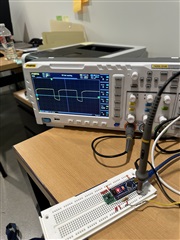
Without tmp1826 connected:

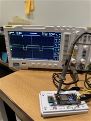
with tmp1826 connected:

test circuit:

code:

int tmp_pin = 16;

void setup() {
  Serial.begin(9600);
 
  sendReset(tmp_pin);
}

void loop() {
}

void sendReset(int pin) {
  Serial.print("Sending RESET to TMP1826...\n");

  pinMode(tmp_pin, OUTPUT);
  digitalWrite(tmp_pin, HIGH); // Start with the line high
  delay(10); // Wait for 10 milliseconds to ensure the line is seen as high
  digitalWrite(tmp_pin, LOW);
  delayMicroseconds(480);
  digitalWrite(tmp_pin, HIGH);

  //wait for response
  pinMode(pin, INPUT);

  while(digitalRead(pin) != 0);
  while(digitalRead(pin) != 1);

  Serial.print("Response to RESET received from TMP1826\n");
}

void sendBit(int pin, bool bitValue) {
    digitalWrite(pin, LOW);
    if(bitValue == 0x00) {
        // tWR0L
        delayMicroseconds(60);
    } else {
        // tWR1L
        delayMicroseconds(2);
    }
    digitalWrite(pin, HIGH);
    delayMicroseconds(2); // tREC
}

void sendByte(int pin, uint8_t byteValue) {
    for (int i = 0; i < 8; i++) {
        sendBit(pin, (byteValue >> i) & 0x01);
    }
}

bool readBit(int pin) {
    //digitalWrite(pin, LOW);
    delayMicroseconds(2); // tRL
    digitalWrite(pin, HIGH);
    delayMicroseconds(1);
    pinMode(pin, INPUT);
    delayMicroseconds(1); // tMSP
    bool bitValue = digitalRead(pin);
    delayMicroseconds(45); // Remainder of the slot time
    return bitValue;
}

uint8_t readByte(int pin) {
    uint8_t value = 0;
    for (int i = 0; i < 8; i++) {
        if (readBit(pin)) {
            value |= (1 << i);
        }
    }
    return value;
}


  • Hi Bennett,

    480us is the minimum pulse width. Have you measured the pulse width produced by the ESP8266 compared to the Arduino? You may need to provide more margin to cover variation in the MCU or its oscillator.

    Your oscilloscope shows a logic level issue. Does this also present itself on Arduino? There may be a significant difference in how the two MCUs are able to switch their GPIO modes. What is the voltage level, and does it meet TMP1826 VIL spec?

    thanks,

    ren

  • Hi Ren,

    I've tested the ESP8266 setup and Arduino setup with the oscilloscope measuring before and after the resistor on both. Here are the results:

    Arduino (measured before resistor):

    Arduino (measured after resistor):

    ESP8266 (measured before resistor):

    ESP8266 (measured after resistor):

    It seems like both are exactly the same, except for the voltage. The Arduino uses 5v and is set up with a 2.2k ohm resistor and the ESP8266 uses 3.3v and is set up with a 1k ohm resistor, and both meet the VIL spec. The response is visible on the oscilloscope when measured after the resistor. 

    Here is my implementation of the reset function:

    void sendReset(int pin) {
      Serial.print("Sending RESET to TMP1826...\n");

      pinMode(tmp, OUTPUT);
      digitalWrite(tmp, HIGH); // Start with the line high
      delay(2); // Wait for 1 millisecond to ensure the line is seen as high
      digitalWrite(tmp, LOW);
      delayMicroseconds(500); // length of reset pulse
      digitalWrite(tmp, HIGH);

      //wait for response
      pinMode(pin, INPUT);

      while(digitalRead(pin) != 1);
      while(digitalRead(pin) != 0);

      Serial.print("Response to RESET received from TMP1826\n");
    }
    Note that the code doesn't hang when a 1 is waitied for before a 0, like this:
    while(digitalRead(pin) != 1);
    while(digitalRead(pin) != 0);
    But it does hang when the 0 is waited for before the 1, as in the "Implementing Host Controller" document:
    while(GPIORead(GPIO.IN) != 0);
    while(GPIORead(GPIO.IN) != 1);
    The result of digitalRead(pin) is 1 then quickly flips to 0. 
  • I've been working on the issue more and determined that I incorrectly copied the power supply schema, so disregard what I said about measuring before or after the resistor. I've corrected the mistake, and now the reset code works as expected (in the order the waits are in the "Implementing Host Controller" document. I'm still having trouble reading the temperature bytes, however. 

    This code here

    // Send Bus Reset
      sendReset(tmp);
      // Send SKIP ADDRESS command
      sendByte(tmp, 0xCC);
      // Send TEMP CONVERT function
      sendByte(tmp, 0x44);
      // Wait for tCONV = 5.5 ms
      delay(6);
      // Send Bus Reset
      sendReset(tmp);
      // Send SKIP ADDRESS command
      sendByte(tmp, 0xCC);
      // Send READ SCRATCHPAD-1 function
      sendByte(tmp, 0xBE);
      // Read two bytes of temperature data
      uint8_t TempLSB = readByte(tmp);
      uint8_t TempMSB = readByte(tmp);

      Serial.print("Received temp data:");
      Serial.print(TempLSB);
      Serial.print(", ");
      Serial.print(TempMSB);
      Serial.print("\n");
    only outputs 255, 255 for TempLSB and TempMSB. Another user had the same issue on a different forum post, but the only explanation provided was a problem with their circuit.
  • It looks like you have the right idea sending reset, skipaddr, convert temp commands followed by the delay, reset, skipaddr and read scratchpad. However, I can't verify that the underlying library that you're using is correct. Can you show me the bus activity when the code runs? Do you have a logic analyzer that can decode 1-Wire? I have the Digilent AD2 which can do it.

    For reference, TI provides a TMP1826 driver in ASCStudio, but you have to provide code for a hardware abstraction layer.

    https://dev.ti.com/sysconfig/index.html?product=ascstudio&module=/ti/sensors/tempsensor/TMP1826

    There is also TMP1826 example code for TI MCUs which performs the hardware abstraction for those MCUs, as an example.

    https://www.ti.com/tool/download/TMP1826-1-WIRE-CODE

    thanks,

    ren

  • I have tried using the TMP1826 driver code provided in ASCStudio, and writing my own hardware abstraction layer. I get the temperature 4095.94, which I assume is the converted version of 255, 255. I've checked all of the timing values, even downloading the code for the TI MCUs and checking the logic and timing there, everything matches up. I don't have access to an oscilloscope right now, but when I do I'll compare what the oscilloscope data looks like from my test circuit compared to the evaluation module. For now, here is my code in case there are any mistakes. My implementation for the reset command is the only thing that isn't copied directly from the TI resources, but I consistently get the correct reset behavior. Here is my mcu.cpp with all of my hardware abstraction implementations:

    /*
     *  Include Generic Header Files Here
     */
    #include <stdint.h>
    #include <stdbool.h>
    #include <stddef.h>

    #include "mcu.h"

    /*
     *  Include MCU Specific Header Files Here
     */
    #include <Arduino.h>
    #include <limits.h>


    /********* MCU SPECIFIC ONEWIRE CODE STARTS HERE **********/
    bool mcu_OneWireOverdrive = false;

    void mcu_OneWireInit(uint8_t busId)
    {
        /* Add MCU specific init necessary for OneWire to be used */

        //Implementation:
        Serial.begin(9600);

        /* Wait 2ms for tINIT after SDQ rises */
        mcu_msWait(2);
    }

    void mcu_txOneWireReset(uint8_t busId)
    {
        pinMode(2, OUTPUT); // led overdrive indicator pin
        digitalWrite(2, mcu_OneWireOverdrive);

        Serial.print("Sending reset...\n");

        bool answerToReset;
        if (mcu_OneWireOverdrive) {
           
            /* Add code for Transmit 48us Overdrive Reset */

            // Implementation:
            pinMode(busId, OUTPUT);
            digitalWrite(busId, LOW);
            delayMicroseconds(48);
            digitalWrite(busId, HIGH);

            /* Add code for Receive ATR and store it in boolean answerToReset */

            // Implementation:
            int timeout = 10000;
            int i = 0;
            pinMode(busId, INPUT);
            while(digitalRead(busId) != 0) {
                if (i >= timeout) {
                    answerToReset = false;
                    break;
                } else {
                    i++;
                }
            };
            while(digitalRead(busId) != 1) {
                if (i >= timeout) {
                    answerToReset = false;
                    break;
                } else {
                    i++;
                }
            };
            if (i < timeout) {
                answerToReset = true;
                Serial.print("Received reset response (overdrive)\n");
            }

            /* if no ATR, drop to normal mode and
             * repeat reset before proceeding */
            if (!(answerToReset)) {
                Serial.print("Switching to standard mode...\n");
                mcu_OneWireOverdrive = false;
                mcu_txOneWireReset(busId);
                return;
            }
            mcu_OneWireOverdrive = true;

        } else {
            /* Add code for Transmit 480us Normal Reset */

            // Implementation:
            pinMode(busId, OUTPUT);
            digitalWrite(busId, LOW);
            delayMicroseconds(480);
            digitalWrite(busId, HIGH);

            /* Add code for Receive ATR and store it in boolean answerToReset */

            // Implementation:
            int timeout = 10000;
            int i = 0;
            pinMode(busId, INPUT);
            while(digitalRead(busId) != 0) {
                if (i >= timeout) {
                    answerToReset = false;
                    break;
                } else {
                    i++;
                }
            };
            while(digitalRead(busId) != 1) {
                if (i >= timeout) {
                    answerToReset = false;
                    break;
                } else {
                    i++;
                }
            };
            if (i < timeout) {
                answerToReset = true;
                Serial.print("Received reset response (standard)\n");
            }
           
            /* If no answer to reset, repeat reset command until device is detected*/
            if (!(answerToReset)) {
                mcu_OneWireOverdrive = false;
                mcu_txOneWireReset(busId);
                return;
            }
        }
    }

    void mcu_txOneWireByte(uint8_t busId, uint8_t dataToWrite)
    {
        uint8_t count;
        // Shift bits LSB to MSB
        for(count=0; count<8; count++)
        {
            mcu_txOneWireBit(busId, (dataToWrite >> count) & 0x01);
        }
    }

    uint8_t mcu_rxOneWireByte(uint8_t busId)
    {
        uint8_t count;
        uint8_t rxbyte = 0x00;
        // Shift bits LSB to MSB
        for(count=0; count<8; count++)
        {
            rxbyte |= (mcu_rxOneWireBit(busId) << count);
        }

        return rxbyte;
    }

    void mcu_txOneWireBit(uint8_t busId, uint8_t dataToWrite)
    {
        if (mcu_OneWireOverdrive) {
            /* Add code for transmit bit at overdrive timing*/

            // Implementation:
            // If logic '0' then set GPIO to 0 and wait for tWR0L
            if(dataToWrite == 0x00)
            {
                pinMode(busId, OUTPUT);
                digitalWrite(busId, 0);
                // Wait for tWR0L = 9 - 10 us
                mcu_usWait(9);
            }
            // If logic '1' then set GPIO to 0 and wait for tWR1L
            else if(dataToWrite == 0x01)
            {
                pinMode(busId, OUTPUT);
                digitalWrite(busId, 0);
                // Wait for tWR1L = 1 - 2 us
                mcu_usWait(1);
            }
            // Release the GPIO
            pinMode(busId, OUTPUT);
            digitalWrite(busId, 1);
            // Wait for tREC = 2 us
            mcu_usWait(2);

        } else {
            /* Add code for transmit bit at normal timing*/

            // Implementation:
            // If logic '0' then set GPIO to 0 and wait for tWR0L
            if(dataToWrite == 0x00)
            {
                pinMode(busId, OUTPUT);
                digitalWrite(busId, 0);
                // Wait for tWR0L = 60 - 120 us
                mcu_usWait(60);
            }
            // If logic '1' then set GPIO to 0 and wait for tWR1L
            else if(dataToWrite == 0x01)
            {
                pinMode(busId, OUTPUT);
                digitalWrite(busId, 0);
                // Wait for tWR1L = 2 - 15 us
                mcu_usWait(2);
            }
            // Release the GPIO
            pinMode(busId, OUTPUT);
            digitalWrite(busId, 1);
            // Wait for tREC = 2 us
            mcu_usWait(2);
        }
    }

    uint8_t mcu_rxOneWireBit(uint8_t busId)
    {
        /* Add code for receive bit and return result */
       
        if (mcu_OneWireOverdrive) {
            // Implementation:
            uint8_t rxbit;
            // Send the falling edge to begin the read
            pinMode(busId, OUTPUT);
            digitalWrite(busId, 0);
            // Wait for tRL = 2 - 3 us and release the bus
            mcu_usWait(2);
            digitalWrite(busId, 1);
            // Wait for tRC and sample the state of the bus
            mcu_usWait(1);
            pinMode(busId, INPUT);
            rxbit = digitalRead(busId);
            // Wait for remainder of the slot time (tSLOT-tMSW)
            mcu_usWait(8);
            return(rxbit);
        } else {
            // Implementation:
            uint8_t rxbit;
            // Send the falling edge to begin the read
            pinMode(busId, OUTPUT);
            digitalWrite(busId, 0);
            // Wait for tRL = 2.5 - 5 us and release the bus
            mcu_usWait(3);
            digitalWrite(busId, 1);
            // Wait for tRC and sample the state of the bus
            mcu_usWait(1);
            pinMode(busId, INPUT);
            rxbit = digitalRead(busId);
            // Wait for remainder of the slot time (tSLOT-tMSW)
            mcu_usWait(60);
            return(rxbit);
        }
    }

    void mcu_OneWireSetOverdrive(bool val)
    {
        mcu_OneWireOverdrive = val;
        /* Add code to configure mcu timing, if needed */
    }
    /********* MCU SPECIFIC ONEWIRE CODE ENDS HERE **********/


    /********* MCU SPECIFIC DELAY CODE STARTS HERE ************/
    void mcu_msWait(uint16_t msWait)
    {
        /*
         *  Add MCU specific wait loop for msWait. The unit is in milli-seconds
         */

        //Implementation:

        delay(msWait);
    }

    void mcu_usWait(uint16_t usWait)
    {
        /*
         *  Add MCU specific wait loop for usWait. The unit is in micro-seconds
         */

        //Implementation:

        delayMicroseconds(usWait);
    }
    /********* MCU SPECIFIC DELAY CODE ENDS HERE ************/


  • Hi Bennet,

    Ren will be out of office through 2/26. Please allow some time for him to respond to the thread to try and solve you issue. Thank you.

    Best regards,

    Simon Rojas

  • In the case of WR1L, you must also wait the remainder of the tSLOT time.

    Your implementation is known as bit banging, and it may not be portable or viable on some platforms. This is because actual hardware timing can vary significantly from expectation. It will be harder to implement at Overdrive speeds, if you have been enabling it. However, the published code TMP1826-1-WIRE-CODE does provide a working "GPIO" or bit bang example. It also provides working examples that use SPI or UART for the abstraction layer. I personally chose to use UART abstraction when I worked with these devices. 

    At any rate, it's essential that we evaluate your timing on an oscilloscope or logic analyzer.

    thanks,

    ren

  • Hi Ren, I have very good news. I've solved the issue, the problem seemed to be with the reset command. I'm not sure exactly what about the reset command was incorrect, but as I was porting the gpio driver code for the c2000 mcu to work with the esp8266 it started reading the correct temperature as soon as I replaced my reset implementation with the slightly altered function from the c2000 driver code. The only explanation that I can come up with is that I had the reset timing wrong and I was sending a standard reset pulse then overdrive everything else or vice versa, but looking over my implementation it seems like it's correct so I'm not sure. If anyone else comes across this thread, here is my mcu.h code, the singlewire_common.h file is from the c2000 onewire code. Thank you very much for your help, Ren.

    /*
     *  Include Generic Header Files Here
     */
    #include <stdint.h>
    #include <stdbool.h>
    #include <stddef.h>

    #include "mcu.h"

    /*
     *  Include MCU Specific Header Files Here
     */
    #include <Arduino.h>
    #include <limits.h>

    #include <singlewire_common.h>

    /********* MCU SPECIFIC ONEWIRE CODE STARTS HERE **********/
    bool mcu_OneWireOverdrive = false;

    void mcu_OneWireInit(uint8_t busId)
    {
        /* Add MCU specific init necessary for OneWire to be used */

        //Implementation:
        Serial.begin(9600);

        /* Wait 2ms for tINIT after SDQ rises */
        mcu_msWait(2);
    }

    void mcu_txOneWireReset(uint8_t busId)
    {
        pinMode(2, OUTPUT); // led overdrive indicator pin
        digitalWrite(2, mcu_OneWireOverdrive);

        Serial.print("Sending reset...\n");
       
        /* Add code for Transmit 48us Overdrive Reset */

        // Implementation:
        pinMode(busId, OUTPUT);
        // Send Reset to device
        digitalWrite(busId, 0);
        if(mcu_OneWireOverdrive)
        {
            delayMicroseconds(H2D_RESET_OVD);
        }
        else
        {
            delayMicroseconds(H2D_RESET_STD);
        }
        digitalWrite(busId, 1);

        pinMode(busId, INPUT);

        // Wait for Response to Reset
        if(mcu_OneWireOverdrive)
        {
            delayMicroseconds(H2D_PDH_OVD);
        }
        else
        {
            delayMicroseconds(H2D_PDH_STD);
        }


        // Now Sample the Line for Being low
        while(digitalRead(busId) != 0);

        // Wait for 60 us minimum
        if(mcu_OneWireOverdrive)
        {
            delayMicroseconds(H2D_PDL_OVD);
        }
        else
        {
            delayMicroseconds(H2D_PDL_STD);
        }

        // Now Sample the Line for Being low

        while(digitalRead(busId) != 1);

        pinMode(busId, OUTPUT);


        // Wait for 480 us minimum
        if(mcu_OneWireOverdrive)
        {
            delayMicroseconds((H2D_RSTH_OVD-H2D_PDL_OVD));
        }
        else
        {
            delayMicroseconds((H2D_RSTH_STD-H2D_PDL_STD));
        }
    }

    void
    mcu_txOneWireByte(uint8_t busId, uint8_t ByteValue)
    {
        uint8_t uiCount;

        // Send data LSB first
        for(uiCount=0;uiCount<8;uiCount++)
        {
            if(((ByteValue >> uiCount) & 0x01) == 0x01)
            {
                mcu_txOneWireBit(busId, 1);
            }
            else
            {
                mcu_txOneWireBit(busId, 0);
            }
        }
    }

    uint8_t mcu_rxOneWireByte(uint8_t busId)
    {
        uint8_t uiCount;
        uint8_t retByte=0x0;

        // Get Data LSB first
        for(uiCount=0;uiCount<8;uiCount++)
        {
            retByte |= mcu_rxOneWireBit(busId) << uiCount;
        }

        return(retByte);
    }

    void mcu_txOneWireBit(uint8_t busId, uint8_t dataToWrite)
    {

        if(dataToWrite)
        {
            // Send Bit-1 to device and wait for slot time
            digitalWrite(busId, 0);
            if(mcu_OneWireOverdrive)
            {
                delayMicroseconds(H2D_WR1_OVD);
            }
            else
            {
                delayMicroseconds(H2D_WR1_STD);
            }
            digitalWrite(busId, 1);
            if(mcu_OneWireOverdrive)
            {
                delayMicroseconds((H2D_SLOT_OVD-H2D_WR1_OVD));
            }
            else
            {
                delayMicroseconds((H2D_SLOT_STD-H2D_WR1_STD));
            }
        }
        else
        {
            // Send Bit-0 to device and wait for slot time
            digitalWrite(busId, 0);
            if(mcu_OneWireOverdrive)
            {
                delayMicroseconds(H2D_WR0_OVD);
            }
            else
            {
                delayMicroseconds(H2D_WR0_STD);
            }
            digitalWrite(busId, 1);
            if(mcu_OneWireOverdrive)
            {
                delayMicroseconds((H2D_SLOT_OVD-H2D_WR0_OVD));
            }
            else
            {
                delayMicroseconds((H2D_SLOT_STD-H2D_WR0_STD));
            }
        }
    }

    uint8_t mcu_rxOneWireBit(uint8_t busId)
    {
        // Send start of bit during read and wait for sampling time
        digitalWrite(busId, 0);
        if(mcu_OneWireOverdrive)
        {
            delayMicroseconds(D2H_RDSTART_OVD);
        }
        else
        {
            delayMicroseconds(D2H_RDSTART_STD);
        }
        digitalWrite(busId, 1);

        if(mcu_OneWireOverdrive)
        {
            delayMicroseconds((D2H_RDSAMPLE_OVD-D2H_RDSTART_OVD));
        }
        else
        {
            delayMicroseconds((D2H_RDSAMPLE_STD-D2H_RDSTART_STD));
        }

        pinMode(busId, INPUT);

        if(digitalRead(busId) == 1)
        {
            if(mcu_OneWireOverdrive)
            {
                delayMicroseconds((H2D_SLOT_OVD-D2H_RDSAMPLE_OVD));
            }
            else
            {
                delayMicroseconds((H2D_SLOT_STD-D2H_RDSAMPLE_STD));
            }
            pinMode(busId, OUTPUT);
            return 1;
        }
        else
        {
            if(mcu_OneWireOverdrive)
            {
                delayMicroseconds((H2D_SLOT_OVD-D2H_RDSAMPLE_OVD));
            }
            else
            {
                delayMicroseconds((H2D_SLOT_STD-D2H_RDSAMPLE_STD));
            }
            pinMode(busId, OUTPUT);
            return 0;
        }
    }

    void mcu_OneWireSetOverdrive(bool val)
    {
        mcu_OneWireOverdrive = val;
        /* Add code to configure mcu timing, if needed */
    }
    /********* MCU SPECIFIC ONEWIRE CODE ENDS HERE **********/


    /********* MCU SPECIFIC DELAY CODE STARTS HERE ************/
    void mcu_msWait(uint16_t msWait)
    {
        /*
         *  Add MCU specific wait loop for msWait. The unit is in milli-seconds
         */

        //Implementation:

        delay(msWait);
    }

    void mcu_usWait(uint16_t usWait)
    {
        /*
         *  Add MCU specific wait loop for usWait. The unit is in micro-seconds
         */

        //Implementation:

        delayMicroseconds(usWait);
    }
    /********* MCU SPECIFIC DELAY CODE ENDS HERE ************/