This thread has been locked.

If you have a related question, please click the "Ask a related question" button in the top right corner. The newly created question will be automatically linked to this question.

TMP114: TMP114

Part Number: TMP114

Hello -

I am considering the TMP114 for my application because of the low thermal resistance between the junction and top case.  Are there any guidelines for how close to the object the TMP114 should be placed?  I guess closer is better, but wonder if you can point me to any documentation that helps quantify this.  I am also considering a non-conductive thermal paste between the case and the object to be sensed and wonder if there is any guidance on this approach.  I did see the post about using thermal epoxy and the associated errors that can introduce.  Are there any concerns with using thermal paste as an interface material?

Regarding accuracy, I have a question about Figure 7-1 of the datasheet.  Can I consider the temperature error to follow the black line when averaging is turned on for sample rates of 31.25ms - 2s?

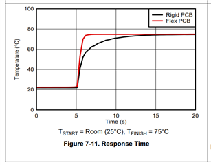
Regarding response time, can I consider the parameter (tLIQUID Response Time (Stirred Liquid)) to be represented by Figure 7-11?

Thank you,

J

  • Hello Jason,

    I would refer to the following document for best practices for sensor placement. As for using thermal paste, I would suggest avoiding it as due to the ultra-thin profile of the device, it will most likely be susceptible to mechanical strain from the paste which would compromise its accuracy. I would refer to the PCB guidelines I linked earlier and start at page 18 as it discusses some recommended practices for measuring the temperature of a component.

    In regards to your question about accuracy, no, your results would not be similar to Figure 7-1 if thermal paste is used, since the strain could have a negative impact on the device's accuracy.

    Lastly for response time, yes, the tLiquid parameter is associated with Figure 7-11.


    Hope this answers your questions!


    Regards,

    Harry Gill

    PCB Guidelines linked again for your convenience: www.ti.com/.../snoa967a.pdf

  • Hi Harry,

    Thank you for the reply.

    I did not find anything in the document that is applicable to the TMP114 since it is sensing temperature through the top case.  The examples I saw beginning on page 18 are discussing similar sensors that conduct temperature through the bottom of their package.  I would like to understand the effect on performance when there is an air gap between top of the TMP114 and the object that is being sensed.

    If I do not use thermal paste, can I consider the temperature error of a single TMP114 to follow the black line in Figure 7-1 of the datasheet when averaging is turned on for sample rates of 31.25ms - 2s?

    Thank you,

    J

  • Hello Jason,

    Try this document. This one is specifically focuses on Under-Component Monitoring, particularly involving the TMP114 (start from page 5) if that's what you're intending to do. Otherwise, we don't have any data which quantifies the impact of an air gap's size in relation to its accuracy at this time. 

    As for the temperature error with Figure 7-1, if you do not use thermal paste and run at 1.8V, the temperature error of your TMP114 should follow the black line (voltage average) in the graph. 

    Regards,

    Harry Gill

  • Thank you Harry.  I have seen that document and will read through it again.

    Do you anticipate running any tests that would quantify the influence of the air gap on accuracy and response time?

    -J

  • Hello Jason,

    We don't have any immediate plans for conducting these tests but we may have something in the future. However, I don't think the air gap should have an impact on the accuracy of the part as long as there is no other heat source nearby which could impact the measurement. As for thermal response the gap length could certainly have an impact, but as of right now we don't have any content on this to quantify it.

    Regards,

    Harry Gill