Hi,
Is there any software API to know RF is using VCO1 or VCO2?
The rfGetProfileConfig() looks only get the application profile, not the RF status itself.
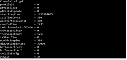
According pfVcoSelect = 0, it seems like we use VCO1 config. But when I set start frequency = 76.2GHz and BW= 2GHz,
the system still can work correctly. (Frequency range is 76.2 ~ 78.5 GHz)
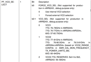
According ICD document description, the VCO1 range is 76~77GHz, so It not make sense.
Therefore, can you tell us how to determinate which VCO is using in RF?