This thread has been locked.

If you have a related question, please click the "Ask a related question" button in the top right corner. The newly created question will be automatically linked to this question.

AWR1843AOPEVM: Questions about schematics

Part Number: AWR1843AOPEVM
Other Parts Discussed in Thread: TMP112

Hello, 

I have the followin questions about the schematics of AWR1843AOPEVM (PROC106B). 

1) There is a temperature sensor IC (U5; TMP112) on the EVM board. 

 What temperature does this IC sense and in what cases does it generate an alert?

2) There is a EEPROM (U6; CAT24C08TDI) on the EVM board. 

 What is the use for this EEPROM? Please let me know an example. 

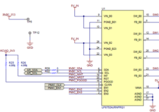
3) There is PMIC(U1; LP87524JRNFRQ1) on the EVM board. 

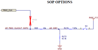
 The PMIC has an external clock input pin (3pin). It is described "Connect to ground if external clock is not used." on the datasheet. 

 But the external clock input pin is not connected in GND in the schematics of AWR1843AOPEVM. (Please see the image)

 Please let me know why the external clock input pin is not connected to GND. 


Please advise, 

Thanks and regards, 

Shoko 

  • Dear Shoko - 

    Thanks for the post and welcome to E2E! 

    A1. The TMP112 (U5) is a digital temp sensor that will measure the general temperature of the board, where it is placed on the PCB. The ALERT pin is open drain, active low signal. From page 23 of the TMP112 datasheetIn Interrupt mode (TM = 1), the Alert pin is activated when the temperature exceeds T(HIGH) or goes below T(LOW) registers. The Alert pin is cleared when the host controller reads the temperature register. You can also read on into page 24, where the Thermostat mode is discussed further and page 26, where high and low limit setting is discussed)

    A2. The I2C accessible EEPROM https://www.onsemi.com/pdf/datasheet/cat24c01-d.pdf can be used to store small amount of information, as user might see fit to do. I found another E2E post about this and in there it was stated there was no specific example in the SDK for usage beyond having I2C driver available. 

    A3. I see your point about the net PMIC_CLK, because R103 is not populated. This device is configurable for using internal or external clock, so in this case, the firmware would handle this, and while it looks to be a technical mistake / against PMIC datasheet recommendation, it does not affect the operation of the system as a result, because the PMIC is not 'looking' for an input there. See page 21 of the LP87524 DS