This thread has been locked.

If you have a related question, please click the "Ask a related question" button in the top right corner. The newly created question will be automatically linked to this question.

TMCS1108: Designing with TMCS1108

Part Number: TMCS1108
Other Parts Discussed in Thread: TMCS1123, TLV840-Q1, TPS3808E-Q1, AMC23C14

Hello Team,
We are planning to use the current sensor TMCS1108 in one of our products to measure the DC current flowing to a motor.
The maximum current to the motor will be 4A only.
The output (Vout) of the IC will be given to the MCU through an ADC.
In case of short circuit event/ or motor stuck, we need to turn of the power supply immediately.
If we are using the MCU to turn of the power supply, it will take more time and by that time the motor may get damaged.
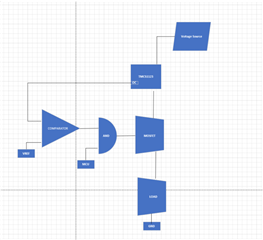
So we are planning to use a comparator at the output of the device TMCS1108 and if the voltage at the output (corresponding to the short circuit current) is higher than a voltage set at the other terminal of the comparator, the comparator will turn of the MOSFET and thereby stopping the current flow.
An AND gate will be connected at the output of the comparator and the MOSFET driver and one of the input of the AND gate will be controlled by the MCU since we need MCU also to control the motor.
Can anyone comment on this architecture?

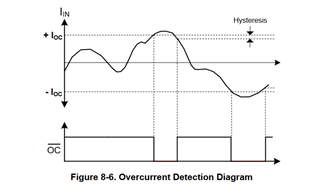
Also, during a short circuit event, the comparator will turn off the MOSFET Driver and thus the current flow is stopped.
And when the current flow stops, the comparator output will go high and this cycle repeats.
Is there any solution to solve this issue?
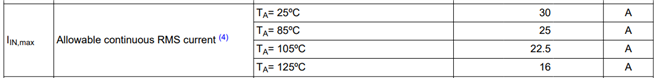
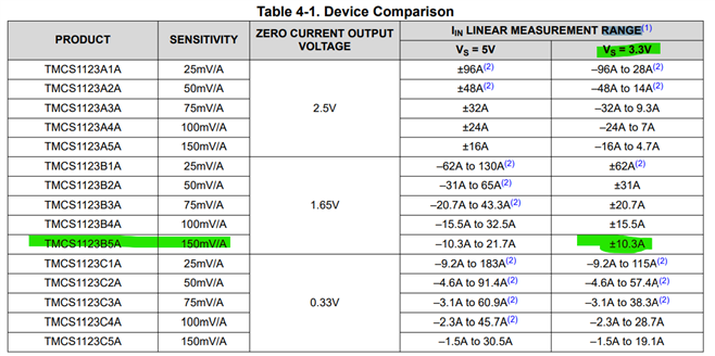
Instead of using comparator, I hope I can use hall based current sensors with ALERT pin outputs.
But still the issue mentioned above persist.
Please correct me if I am wrong.

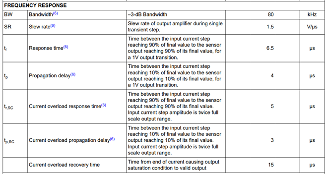
Also, what will happen if a current higher than the rated current is flowing through the device. Will this damage the device as this is a hall sensor?

Looking for your reply.

  • Hello,

    Thank you for your post. 

    Unless you want to use an isolated comparator, the speed of the signal chain will depend on the TMCS1108. The output is limited by the TMCS1108 input sampling rate of 250kHz. 

    Below you will see for the current overload response times and propagation delays which will be important for your short circuit current detection. You will see a ~7us total delay not including the recovery from the current overload condition.  

    If you exceed the maximum continuous input current then we cannot warranty the performance of the device during this time. Please ensure that the junction temperature is within the ABS max ratings table to ensure the device is not damaged.

    So if I were to recommend a device it would be the TMCS1123B5A. this would give you the OC output pin that you can set with your VOC input pin. 

    This is the cleanest way to implement this.

    I also need to know what your minimum measuring current is and your available supply voltages to ensure my proposed solution will meet your needs. 

    Best Regards,

    Joe

  • Hello Joe,
    Thank you for your reply.


    As per the image above, the OC pin is recovered only after the over current event is removed.
    Please correct me if I am wrong.
    Suppose this OC pin is used to control the MOSFET Gate, and the MOSFET is turned off at an over current event, the OC goes high again and this cycle repeats.
    Please correct me if I am wrong.
    I think I need some sort of delay after an over current event is detected.

    Looking for your reply.


  • Hello, 

    Yes, the OC pin recovers only after the overcurrent condition is removed. This active low, open-drain output will recover after about 300ns. 

    I would make sure to note the required recovery time. 

    Does this make sense?

    Thanks,

    Joe

  • Hello Joe,
    Thank you for your reply.

    Can you please clarify the doubts I am having?
    1). The OC pin will recover after 300nS after the over current condition is removed. Please correct me if I am wrong.
    2). If we are planing to use the OC pin to enable or disable the current flow through the device (by controlling the Gate of the MOSFET through a comparator and ANDing with the control signal from the MCU), during an over current event, the OC pin goes low and this turn the MOSFET off which stops the current flow through the device and the device's OC pin will go high again and this cycle repeats.
    I believe there should be some delay after the OC pin is pulled to GND and its recover. This time should be enough to take necessary action by the MCU. Else the the MOSFET will continue to ON and OFF. Please correct me if I am wrong.

  • Hi, 

    I would like to add some clarification here. I meant to point out the variance in the propagation delay of this OC pin. The maximum prop delay for this output (OC) is 250ns high to low.

    The current overload recovery time is specifying the recovery time of the output amplifier.

    This recovery time will only come into play if you saturate the output of the amplifier. 

    I was providing you with the recovery time of the output amplifier during a current overload condition of 300ns.

    As far as your circuit, there are comparator cookbooks and resources to help you construct the FET switch circuit. 

    https://www.ti.com/lit/ab/snoaa20/snoaa20.pdf 

    My only question is are you trying to clean up the OC signal? Or do you have a variable reference on one of the comparator inputs?

    I am asking because OC output signal from the TMCS1123 will also be a digital output. You can use the digital output of the TMCS1123 to control a gate driver as well. 

    So to clarify, you can implement what you drew above, however, I think you can simplify the FET control.

    Best Regards,

    Joe

  • Hello Joe,
    Thank you for your reply.

    I am asking because OC output signal from the TMCS1123 will also be a digital output. You can use the digital output of the TMCS1123 to control a gate driver as well. 

    If I use the OC pin of the TMCS1123 only, the MCU cannot control the current to the load.
    That is why we are using an AND gate IC.
    The MOSFET will be on only when both the input conditions (signal from the MCU, and no over current condition) is satisfied.
    You are correct, we don't need to use the comparator since the OC pin is a digital pin.
    The IC TMCS1108 doesn't have an OC pin. That is why we are using a comparator.
    During over current event, the OC pin goes low and even when the MCU control pin is high, the MOSFET will turn off resulting no current flow through the hall sensor and the load.
    The MCU control pin can be still high because the MCU has many other task to perform.
    When no current flow through the TMCS1123 device, the device will think the over current condition is removed and the OC pin will again go to high and thereby the MOSFET start to conduct and if the over current condition still exist, the device will again de assert the OC pin and this cycle is repeated.
    The only delay between the over current condition removal and the OC pin low to high is 300nS.
    The MCU cannot act in such a short period of time.
    Is there any circuit or solution to solve this is issue?.
    Like by adding some delay between the OC pin and the comparator and will only come into play during low to high event of the OC pin.
    Can you please comment on this?.

    Some voltage regulators have a feature call hiccup mode in which the device will check whether the over current condition is removed or not.

  • Hello,

    You are absolutely correct about the AND gate. I would implement this with the MCU signal as you mentioned to give you an additional means of controlling the FET in the TMCS1123 design. 

    In terms of the uP, what is the minimum pulse width that it can detect? You can add additional delays to the overcurrent signal path by adding a comparator to the overcurrent signal path or by low pass filtering the output. 

    Another way to slow down the TMCS1123 OC signal is to increase the size of the pull-up resistor on the OC pin since it is an open drain output.

    The only delay between the over current condition removal and the OC pin low to high is 300nS

    By increasing the size of the pull-up resistor on the TMCS1123 OC pin, you will slow down the Low to High transition on the OC pin. Is this an option you have available?

    During over current event, the OC pin goes low and even when the MCU control pin is high, the MOSFET will turn off resulting no current flow through the hall sensor and the load.
    The MCU control pin can be still high because the MCU has many other task to perform.
    When no current flow through the TMCS1123 device, the device will think the over current condition is removed and the OC pin will again go to high and thereby the MOSFET start to conduct and if the over current condition still exist, the device will again de assert the OC pin and this cycle is repeated.
    The only delay between the over current condition removal and the OC pin low to high is 300nS.

    All of the above is correct. 

    I hope the above is helpful.

    Best Regards, 

    Joe

  • Hello Joe,
    Thank you for your reply.

    By increasing the size of the pull-up resistor on the TMCS1123 OC pin, you will slow down the Low to High transition on the OC pin. Is this an option you have available?

    Yes you are correct. By increasing the R in the RC combination, we can increase the time delay to achieve the VIH of the comparator.
    Is there any other solutions I can go with.
    Like by using some power supply monitors like TLV840-Q1.
    We can program the delay (low to high) upto 6.2Seconds.
    Can you please comment on this?

    Looking for your reply

  • Hello,

    I have not seen an overcurrent circuit responding in the order of seconds. Will the rest of your system not get damaged by the 6 second overcurrent state?

    Wouldn't you want to respond quickly or am I missing something?

    Thank you,

    Joe

  • Hello Joe,
    Thank you for your reply.
    Following is the circuit for the supervisor IC TPS3808E-Q1.


    The output of the current monitor IC can be connected to the sense pin.


    Following is the timing diagram of the supervisor IC TPS3808E-Q1

    From the timing diagram it is clear that, when the voltage at the sense pin is lower than the 0.4V Vref, the reset pin will de-assert  immediately (after 50uS). And the  reset pin go to high only after a some delay programmed by the capacitor CT.
    The reset pin will be connected to the input of the AND gate.
    So I hope the circuit will act fast when an over current event is detected.
    Do you think A 50uS delay can damage the rest of the device?.

    Looking for your reply.

  • Hello,

    The most efficient way to propose a design for you is to schedule a meeting. Please reach out to your local FAE and have them schedule a meeting so that we can discuss this potential design in detail. I want to get you the solution you need ASAP.

    If this works for you, please click "This has resolved my issue" on this reply so that the thread is closed.

    I will make myself available when convenient for you.

    Best Regards, 

    Joe

  • Hello, 

    I want to make sure you have received the support you need. Have you been able to reach out to an FAE? If not we can continue this thread with some of my suggestions. 

    Please keep me posted. 

    Thank you,

    Joe

  • Hello Joe,
    Thank you for your reply.
    We decided to use a window comparator like mentioned in the application note Window Comparator Reference Design (ti.com).
    Since the current can flow in both directions.
    The over current will be set at +/-150A.
    The comparator will turn off the MOSFET in case of an over current situation and we will add some delay to turn on the MOSFET after the OC event.
    We can use the IC AMC23C14 as this has an isolation at the output of the TMCS1108

  • Hello,

    Thank you for the information. I will now close this thread but please reopen this thread or create a new one for any support you need on the TMCS1108 or TMCS family of devices. 

    Best Regards, 

    Joe