This thread has been locked.

If you have a related question, please click the "Ask a related question" button in the top right corner. The newly created question will be automatically linked to this question.

IWR6843AOP: People Tracking - track allocation starting late

Part Number: IWR6843AOP

Hello!

I am using the People Tracking Project with the IWR6843AOP in Overhead configuration.

The Sensor is mounted at 3.1m height in parallel to the floor, so no tilt towards azimuth or elevation.

I am transmitting the track including the coordinates that make the track to a local PC where I plot them. I noticed a couple weeks ago, that the tracks take quite a lot of time until they are first allocated. Meaning, with the boundary-/presence-/static boxes set to -4.5/4.5 on X and Y, the tracks usually are not allocated until 2m into the box. I managed to improve that, by reducing the TXBackoff power to the minimum and RX Gain setting to the max, as well as fiddling with the allocation parameters, so that less SNR, and points are required.

This is the configuration that I am using now:

sensorStop
flushCfg
dfeDataOutputMode 1
channelCfg 15 7 0
adcCfg 2 1
adcbufCfg -1 0 1 1 1
lowPower 0 0
profileCfg 0 61.2 60.00 17.00 50 0 0 55.27 1 64 2000.00 2 1 46
chirpCfg 0 0 0 0 0 0 0 1
chirpCfg 1 1 0 0 0 0 0 2
chirpCfg 2 2 0 0 0 0 0 4
frameCfg 0 2 224 0 120.00 1 0
dynamicRACfarCfg -1 10 1 1 1 8 8 6 4 4.00 6.00 0.50 1 1
staticRACfarCfg -1 4 4 2 2 8 16 4 6 6.00 13.00 0.50 0 0
dynamicRangeAngleCfg -1 7.000 0.0010 2 0
dynamic2DAngleCfg -1 5 1 1 1.00 15.00 2
staticRangeAngleCfg -1 0 1 1
fineMotionCfg -1 0 2.0 10 2
antGeometry0 -1 -1 0 0 -3 -3 -2 -2 -1 -1 0 0
antGeometry1 -1 0 -1 0 -3 -2 -3 -2 -3 -2 -3 -2
antPhaseRot 1 -1 1 -1 1 -1 1 -1 1 -1 1 -1
fovCfg -1 64 64
compRangeBiasAndRxChanPhase 0 1 0 1 0 1 0 1 0 1 0 1 0 1 0 1 0 1 0 1 0 1 0 1 0
staticBoundaryBox -2 2 -4.5 4.5 0 2.5
boundaryBox -2 2 -4.5 4.5 0 2.5
sensorPosition 3.1 0 90
gatingParam 3 2 2 3 4
stateParam 1 3 12 40 3 400
allocationParam 10 10 0.01 3 1.5 20
maxAcceleration 1 0.1 1
trackingCfg 1 4 800 20 37 33 120 1
presenceBoundaryBox -2 2 -4.5 4.5 0 2.5
sensorStart

This is one track produced with this configuration, where the track starts at ~3m on Y and ends at ~4.1m on Y:

even with the config changed that much, the setup fails to consistently provide tracks that start somewhere close to the boundary box.

The issue is, that It seems fishy to me, that I have to change to stop, config for the overhead version to achieve pretty much the same performance shown in the TI documentation regarding that example project.

Side facts:
I am using a custom PCB that has the IWR mounted, cased in a 3D-printed housing. But temperatures and overall stability of the system are constantly good, so I don't assume an error in the electronics. Also the housing has little to no effects on the performance, I have tried the same setup without case to verify that multiple times.

The hallway, where the sensor is mounted is ~4m wide, which is why the configuration shows -2/2m for the boundary boxes on X.

Thanks in advance for help and assistance!

~ Sebastian

  • Hi Sebastian,

    What does this mean?

    The issue is, that It seems fishy to me, that I have to change to stop, config for the overhead version to achieve pretty much the same performance shown in the TI documentation regarding that example project.

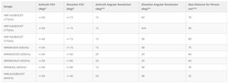
    Based off the FoV, if you mount the sensor at 3.1m, you should be able to detect points starting at 5.4 meters away.  

    https://dev.ti.com/tirex/explore/node?a=1AslXXD__1.00.01.07&node=A__ACvJLhyw8rRPopsPFMtIWw__radar_toolbox__1AslXXD__LATEST&r=1AslXXD__1.00.00.26

    Can you look at the PDF documents here?

    https://dev.ti.com/tirex/explore/node?a=1AslXXD__1.30.01.03&node=A__AIQPG9x7K34A8l4ZELgznA__radar_toolbox__1AslXXD__1.30.01.03

    They have sections on increasing the motion sensitivity in both the tracker and detection layers.

    Best,

    Nate

  • Hi Nate!
    Thanks for your reply. 

    Referring to your question: What I mean by that is, that I would in the first place expect similar performance to the documentation, specifically to the videos and plots shown in the documentation, when applying the same configuration as proposed in the documentation. But what I came across, and therefore the reason I created the above forum post is, that I have to modify the configuration a lot and Im still not getting similar performance. Therefore Im assuming an error in the configuration or somewhere in my setup that I cannot find or have missed in my attempts to improve the performance. 

    Regarding the documents: Thanks for the FoV-table, I was not yet aware of that. But as you propose, I should be able to detect movements up to 5.4 meters away. But with the IWR6843AOP in overhead-mode with the configuration provided above I am struggling to get consistent performance further then ~3.8m. With the stock configuration provided in the Radar toolbox in the Overhead-people-tracking example I am struggling to go past 3m consistently. 

    I have used the "Detection Layer Parameter Tuning Guide for the 3D people tracking Demo" to manipulate the configuration and get to the version I have provided above. 

    What I will do now: I will return to the stock configuration, remove the housing and capture some more tracks and provide you those, so that you can see what the performance looks like on my end. I will also change the stock configuration regarding fine motion detection and try that as well.

    Further thoughts:

    • Since the performance in the limited field of view looks as expected -> angular resolution, range resolution are what I would expect, I am assuming that there is no major electrical defect. I have created the schematics an PCB according to the design rules an guideline provided by TI and used the components (PMIC,...) as suggested by TI.
    • Is it possible, that the limited range is due to any other physical properties in the building? The floor for example is a very thick and dense concrete and very polished surface, which could potentially lead to artifacts reducing the performance?
    • As to be observed in the configuration, I have limited the X-axis in the boundary boxes to -2/2 meters, because the hallway that I am testing the sensor on is that wide. Could that lead to an issue, due to reflections from the walls or something like that?

    Thanks in advance, as stated above, I will provide you with images that visualize the outcome at stock configuration.

    ~ Sebastian

  • Hi Sebastian

    A few thoughts:

    1. Because detections may start at 5.4 meters, I would not expect tracks to allocate at this distance. In the tracker algorithm, it takes a frame or two to get a track to allocate. Perhaps a better metric we can use for assessing the device's angular field of view is the largest angle at which it detects a point. Does that increase past 3.8 meters? You may also consider lowering the detection SNR thresholds to improve this, as points are naturally weaker in power at the edges of the field of view. Keep using your configuration. There are not so many differences between it and the out-of-box, and your scenario (people flow counting in a hallway) may be different from the designed use-case, which is more likely to be stationary people.

    • Is it possible, that the limited range is due to any other physical properties in the building? The floor for example is a very thick and dense concrete and very polished surface, which could potentially lead to artifacts reducing the performance?

    This is possible, but I don't necessarily believe that it is debilitating. Do you see many reflections at the floor? That would be a likely symptom if this is a problem.

    • As to be observed in the configuration, I have limited the X-axis in the boundary boxes to -2/2 meters, because the hallway that I am testing the sensor on is that wide. Could that lead to an issue, due to reflections from the walls or something like that?

    Limiting the x axis boundary box is a good strategy, but it will not affect your overall SNR. In order for the device to assess the angle of arrival of a return, it needs to be able to receive it. Therefore, if you have a corrupting signal at a specific angle, you cannot figure out its angle (which is needed to remove it) without measuring it in the overall received wave.

    Best,

    Nate

  • Hello Nate!

    Since with Monday, I wanted to record the points generated by the overhead_people_tracking example. Since I am not using them in my application, but only the clusters that make up the tracks, I wanted to record the point cloud in the industrial visualizer and replay it to evaluate the performance afterwards to fine-tune the configuration to my needs. 
    But I cannot find a prebuilt replay function within the visualizer itself or anywhere else. (I checked the python code, it states there that the replay function is todo, also the release notes of the current visualizer don't state a replay function. Is there another place to look for?)

    I also tried to build a "replay script" myself, but it seems like the data save functionality in the visualizer is not working as intended, or something else is going wrong, but I am not able to replay the data. 

    Is there a rather quick fix for that, or something easy you could recommend me? If not, I will do my best to use the industrial visualizer and do some screen recordings or something similar and update you at the end of this week regarding progress in terms of better tracking performance.

    Best regards, 

    Sebastian

  • Hi Sebastian,

    Unfortunately the replay function in the industrial visualizer is still "to-do." I'm happy to help you build it though - you would mostly just need to change the calls from uart reads to file reads and so forth.

    I also tried to build a "replay script" myself, but it seems like the data save functionality in the visualizer is not working as intended, or something else is going wrong, but I am not able to replay the data. 

    You should be able to save the data from the visualizer into .bin files in the directory that you run the visualizer from. What toolbox version are you using? The most-recent version should support this. Click the "Save UART" button on the top left.

    Best,

    Nate

  • Hi Nate!

    Up to this point, I tried many many different configurations and what it always comes down to (as it seems) is that with increased transmission power and/or receive gain, the tracking performance increases. Which makes sense of course.

    By going through the Antenna radiation patterns again, I found that the Antenna performance is better when operated at 60GHz then at higher frequencies. Since the standard overhead-3d-people-counting config starts at 61.2GHz I always kept it like that, but reducing the start frequency to 60GHz made a great difference, while sticking to the recommended 10dB txPowerBackoff and 36 as rxGain. But I will still decrease the txPowerBackoff to 2-5dB and the rxGain to 40 for further testing.

    I also tried the BPM mode, which according to the implementation details gives another 3dB of increased transmission power. I was always hesitant in using that, because to my knowledge the BPM MIMO mode is inferior to the TDM MIMO mode in terms of angular resolution. Is that true? We need as high angular resolution as the we can get to make sure we can track as many people as possible at the same time, but since the BPM mode "promises" another 3dB it might be a tradeoff that I am willing to make to make sure that we can track reliably in the -4m to 4m range in X and Y.

    Please supply me some information, if the BPM mode is in fact inferior to the TDM mode.
    Thanks in advance!

    ~ Sebastian


    ----------------- EDIT -----------------
    When using the BPM mode, as well as changing the start frequency to 60GHz, using a 2dB txPowerBackoff and 36 as rxGain I seem to get a reliable track in the -4m to 4m range on X and Y !
    Is there a reason, the startFrequency is set to 61.2 GHz at default?

  • Hi Sebastian,

    Is there a reason, the startFrequency is set to 61.2 GHz at default?

    I would guess that the 61.2 GHz start frequency was set to comply with older frequency regulations in the United States. The 61.0-61.5 GHz band used to be the best band to operate in, but with the new FCC rules, you can operate with higher transmit powers at a variety of sub-bands within the 57-71 GHz band.

    I was always hesitant in using that, because to my knowledge the BPM MIMO mode is inferior to the TDM MIMO mode in terms of angular resolution.

    I am not aware of any angular resolution degradation when using BPM-MIMO.

    When using the BPM mode, as well as changing the start frequency to 60GHz, using a 2dB txPowerBackoff and 36 as rxGain I seem to get a reliable track in the -4m to 4m range on X and Y !

    Can you use 0 dB backoff? That seems like the easiest way to get more transmit power.

    Best,

    Nate

  • Ni Nate!

    Makes sense, then I'll check these bands and make sure Im within them. 

    Ok, if there is no degradation in Angular resolution, I will stick to the BPM Mode.

    I can use 0dB backoff, but all over the documentation it is mentioned to increase it carefully to not create too much multipath reflections... although I guess Im doing the same thing with the BPM-MIMO anyways...

    I guess my Issue is solved then, thanks for your support!

    ~Sebastian