This thread has been locked.

If you have a related question, please click the "Ask a related question" button in the top right corner. The newly created question will be automatically linked to this question.

IWR1642BOOST: vital signs

Part Number: IWR1642BOOST

Hi, I have the following questions looking forward to your answers :

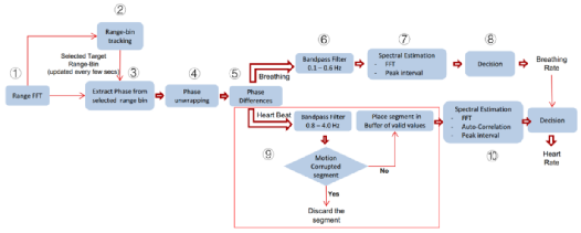
1) When the radar board is transmitted to the respiratory heart rate GUI on the PC through the serial port, which stage is the data in the following figure? Which step is the data given by the radar board and which step is the data processed by the subsequent software?

2) Step 6 is implemented in which code in which file?

3) Respiratory heart rate demo is calculated by GUI software or hardware output to the computer data bin file there, if it is software calculation please ask his source code where?

4) If I want to use the save data of the GUI interface of the driver vital signs demo to save data, what should I do to extract complex range bin drawings?

Thank you so much.

  • Hi,

    1. Entire signal chain depicted in the diagram is implemented within the hardware. GUI only displays the TLV data received

    2. Step 6 is present in dss_vitalSignsDemo_utilsFunc.c

    3. Hardware computes the Heart rate and Breath rate. Source code is present in mmwave automotive toolbox 3.6.0

    4. Hardware sends the Vital signs TLV data through the UART which is used by the GUI. You need to decode the Vital signs TLV format.

    Please refer to the documentation in the vitals signs demo for the TLV format

    Regards

  • Hi,Abhishek,


    If I need to change the frame rate and change the filters, which section of code in which dss/mss file should I change?

    Thank you,

    Liting.

  • Hi,

    Frame rate change is done in the .cfg file and filter changes are done in dss_vitalSignsDemo_utilsFunc.c

    When you change the frame rate, you need to make sure that entre vital signs processing can be done before the next frame is triggered.

    Regards

  • Hi,

    Thank you for your answer.  I would like to ask if I can get the data after each of the above eight steps from the  "dataOutputFromEVM.bin" file saved by the "save data" button of the GUI interface and draw eight figures?

    If so, should the data be drawn from "Vital Signs Output Stats" or "Range Profile(Complex)" of the data TLV structure?
     
    best regards,

    Liting.

  • Hi,

    You can get only the TLV data sent out of the sensor. Data at intermediate steps is not sent out of the IC

    Regards