This thread has been locked.

If you have a related question, please click the "Ask a related question" button in the top right corner. The newly created question will be automatically linked to this question.

AWR2944EVM: Increasing the range beyond 100+ meters and support required for the board.

Part Number: AWR2944EVM
Other Parts Discussed in Thread: AWR2944, , AWR2243

1. In AWR2944 EVM, which parameters in cfg needs to be changed in order to increase the range profile in 3D up-to 150meters with/without any compromise in the resolution?  Please be noted that the example used for testing was awr2944_mmw_demoTDM, and demo visualizer tool. cfg attached.

2. Also, what is the out-of-box demo that needs to be considered to use beyond 100+ meters?

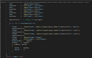
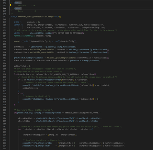
3. Is there any beam steering feature available in AWR2944EVM and if yes where can we find the inbuilt code/demo and how to enable it?

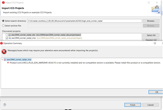
4. Is there any matlab code available with the package of 2944, just like AWR2243 cascade radar?

AWR294X_profile_2024_03_11T09_38_19_597.cfg

  • Hello,

    I recommend to read the below app note to understand how range and range resolution are determined. From there you can derive your own configuration to maximize the range.

    Programming Chirp Parameters in TI Radar Devices (Rev. A)

    Yes, it supports beam stearing. I recommend to read the OOB demo documentation (you must first install the SDK to access these links). Specifically, you can refer to the DDM processing chain details which use the phase shifters.

    C:/ti/mmwave_mcuplus_sdk_04_05_00_02/mmwave_mcuplus_sdk_04_05_00_02/docs/mmwave_sdk_module_documentation.html

    C:/ti/mmwave_mcuplus_sdk_04_05_00_02/mmwave_mcuplus_sdk_04_05_00_02/ti/datapath/dpc/objectdetection/objdethwaDDMA/docs/doxygen/html/index.html

    For AWR294x, we only have some basic matlab scripts to parse and read data in the mmWave Studio folder.

    C:\ti\mmwave_studio_03_01_01_00\mmWaveStudio\MatlabExamples

    Regards,

    Adrian

  • Hi Adrian

    Thanks for providing links.

    We had gone through the specified documents 1. C:/ti/mmwave_mcuplus_sdk_04_05_00_02/mmwave_mcuplus_sdk_04_05_00_02/docs/mmwave_sdk_module_documentation.html but could not find the method to beam steer or change the phase. we had gone through the code which was in the package but could not find how to change in the code for beam steering.

    2. Is there any GUI available for 2944 in order to configure beam steering / phase shifters which is similar to Visualizer tool provided for 1843.

    3. what is the out-of-box demo that needs to be considered to use beyond 100+ meters?

  • Hello,

    For OOB demo at 100+ meters you need to configure an appropriate chirp configuration based on the provided app note to maximize the range. You also need to be aware that the range of an object you can detect will be determined by the RCS of the object and the power/gain of the system (EIRP).

    For the other questions, these need to be answered by our software experts. I will notify them of this thread to help.

    Regards,

    Adrian 

  • Hi Adrian,

    Tried below demo & config:

    1. awr2944_mmw_demoDDM.appimage

    2. profile_3d_3Azim_1ElevTx_DDMA_awr2944_highRange.cfg (As range needed was 100+meters)

    In online demo visualizer gui, not able to see the X-Y plot after loading the cfg (above mentioned). Only was able to see 3-D plot, Range Profile for zero plot, doppler vs range plot and CPU load stats.

    Also wanted to see the height/elevation of the object (Y-Z plot) as in 3-D plot not able to determine the object height as data points gets varying and not providing solid constant points(in vertical Z axis) for constant objects.

    Also, when undergoing High End Corner Radar High-End Corner Radar Reference Design (ti.com). In section 3.1.2  there is a reference to Automotive Toolbox that consist of gui, but couldn't find the gui in the document provided link. Please provide the GUI details so as to capture the objects as described in same document section 3.3.

  • Hi Meher,

    Thank you for your patience! Please find my responses below:

    • In this configuration, we use a DDMA modulation scheme. You can refer to the usage of the per chirp phase shifter module in the mss_main.c file of the demo for AWR2944.
    • We do not have any doc or explanation of performing beamforming on this device. However, you are free to come up with your beam steering algo and waveform design and implement it with the per chirp phase shifter module.
    • You can refer to the High-End Corner Radar SW example in TI's Radar Toolbox for the demo referred in the paper.
    • As for the visualizer, the one you are referring to has been deprecated. You can refer to the following link:

    Regards,

    Kaushik

  • Hi Kaushik,

    How to extract raw data / IQ data directly from the hardware before being processed by DSS. I believe the data that is being received in UART for Out-of-box demos is processed data.

    Also, I'm getting issue when trying to import High end corner radar example project into CCS, screenshot attached below. (Please note that I installed complete mmwave_mcuplus_sdk_04_04_01_02 and verified the path C:\ti\mmwave_mcuplus_sdk_04_04_01_02\mcu_plus_sdk_awr294x_09_00_00_15). Using CCS12.7 version.

    Please let us know if we can schedule a call to discuss regarding this issue.

    Regards

    Meher

  • Hi Meher,

    Thank you for your patience. 

    • You can use the mmWave studio or the LVDS stream feature within the demo to capture the ADC data out using the DCA1000 EVM.
    • You can also take a dump of the ADC buffer if you are looking for just a single chirp of data.
    •  Can you please install the right version of the SDK tools needed to build the demo? You should be able to find the same in the user guide of the application.

    One kind request is that you create new threads when there are separate issues that you require support on so that we can track the same better on our end.

    Regards,

    Kaushik