This thread has been locked.

If you have a related question, please click the "Ask a related question" button in the top right corner. The newly created question will be automatically linked to this question.

DRV5055: Wire Fault Detection Circuit DRV5055

Part Number: DRV5055
Other Parts Discussed in Thread: CC1352R

hello everyone 

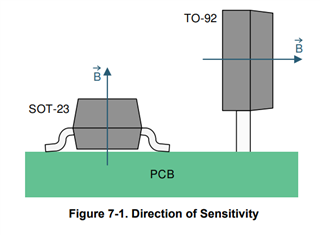
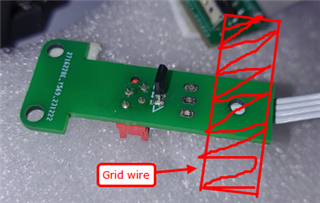
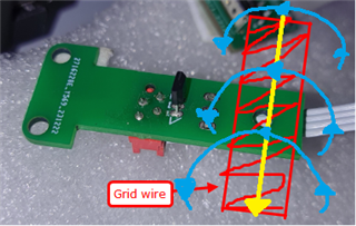
can anyone explain how drv5055 hall effect sensor sense current in the wire or it just sense the breakout of wire ?

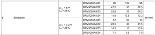
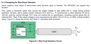
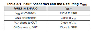
there is some terms given like "output voltage to stay within the VL range" and "current through OUT must not exceed the IO specification," and "Then, if the output voltage is ever measured to be within 150 mV of VCC or GND, a fault condition exists."

application : i have used mcu cc1352r with 3.3v supply  and connected this sensor to its analog gpio, 

how this sensor work and where did i need to connect wire which i want sense the breakout.  

i have tried to understand from datasheet but not find how it works or how to use.

www.ti.com/.../drv5055.pdf

Thanks & Regards

  • Dhruvit,

    Thanks for reaching out on E2E.  DRV5055 will respond to the component of the magnetic field vector which is normal to the sensing element.  

    As the field varies, the sensor output will vary linearly with the change in magnetic flux density.  The source of this field may be a permanent magnet, an electromagnet, or just a current carrying wire.  Following the right hand rule, the field created by the current through the wire will follow this equation:

    • B = (μ0•I) / (2π•r)

    Where

    • μ0 = 4•π•10-7 T•m/A 
    • r = radius from wire (m)
    • I = current in the wire (A)

    If the sensor is placed near enough to a sufficiently large current, then there will be measurable changes at the output of the sensor.  The quality of the measurement will depend on the SNR, and so it will be important to generate a field at the sensor location sufficiently larger than the noise floor of the device.

    Supposing we are operating with a 5V supply, the input referred noise is typically about 0.12 mTpp.  If we assume a radius to the wire of 2 mm, it would require 1.2A of current to exceed the peak-to-peak noise of the sensor.

    An alternative option would be to use a TMCS device to measure current in the wire.  These devices are specially designed to use magnetic sensing to detect currents using Hall-effect technology by routing the current through the package and reducing the value of 'r' significantly.

    https://www.ti.com/sensors/magnetic-sensors/hall-effect-current/overview.html

    Thanks,

    Scott

  • Hi Scott,

    Thanks for your reply. For a clearer understanding, I'm providing a practical overview of the application.

    The DRV5055 is supplied with a 3.3 V supply from the CC1352R MCU's GPIO pin. Its output is connected to the ADC pin. Due to the low power requirement, a GPIO configuration was chosen to avoid using an extra component like a load switch.

    This sensor will be used to measure current in a 3 to 4 cm thick grid line carrying a large amount of electric charge. The voltage on the line is not limited and can be 110, 132, 150, 220, or 400 kV.

    Given sufficient magnetic flux to detect the current, can you advise if it will detect the current or wire breakage by averaging the analog output and applying some value settling mechanism?

    This is prototype pcb where black component is DRV5055 and red indicated area is grid wire position.

    Thanks & Regards

  • Dhruvit,

    It may well be possible in this high power application where such large voltages are involved that the current in the line will create a measurable field for DRV5055.  The main consideration then is to be sure that the direction of the field generated is correct for the package chosen.  In your picture, a TO-92 (LPG) package is used, and a sensor with this orientation would measure the portion of the field vector which is horizontal relative to the picture.  The current in the wire will produce a field similar to what I have sketched

    At the location of the sensor, it is likely that the majority of the field will be in a vertical direction, and so a SOT-23 (DBZ) package would be a better choice.

    In the event that there is no current (possibly caused by a breakage) the sensor would not measure any field, and the output would be approximately Vcc/2.  In the presence of a field, the output will change at a rate which is selectable through the various package options

    This sensitivity will cause the output to respond to the actual magnetic field with a bandwidth of 20kHz. With sufficient field, any variance from Vcc/2 will indicate current in the wire.

    Thanks,

    Scott

  • Hi Scott,

    Thank you for your reply. The product is working on-site, but there are a few minor bugs that I need to identify. I'm unsure if they are hardware-related or firmware-related. I may be mistaken, but based on your previous information, there's plenty of magnetic flux to detect, so that shouldn't be an issue.

    For the packaging, if the firmware has difficulty with the current design, I'm very interested in your suggestion of using the SOT-23 package. I would also personally prefer that option. However, I'm curious why the circuit designer chose the TO-92 package.

    One last question: If there is sufficient electricity or magnetic flux near the sensor, will the output be close to the supply voltage (3.3V) or will it vary due to the analog output nature?

    Thanks & Regards