This thread has been locked.

If you have a related question, please click the "Ask a related question" button in the top right corner. The newly created question will be automatically linked to this question.

TMAG5170-Q1: Sleep mode to active continuous measure mode in TMAG5170 is not working. I mean the data is not changing after continuous measure mode

Part Number: TMAG5170-Q1
Other Parts Discussed in Thread: TMAG5170

Hi Team, 

We are using the TMAG5170-Q1, We are able to get the sensor data when the sensor is operating in DEVICE_CONFIG_OPERATING_MODE_ActiveMeasureMode. 

my application demands data only for 90 second once. So in order to save power I want to  put the TMAG5170 sensor to sleep mode. 

Below is the overall steps: I am doing in application 

1. putSensorToSleepMode()

2. wakeUpSensorFromSleepModeToActiveMeasureMode()

3. do

     {

        read Sensor Data

        delay(90 sec)

     } while (1)

I could not see any change in the sensor data. 

I am attaching my driver code below . 

int8_t enterConfigurationMode()
{
    int8_t retVal = 0xFF;
    // To prevent undefined behavior, this function does not perform its operation
    // when the DATA_TYPE field (address: 0x028-6) is not set to Normal Read Mode (000b)
    if ( DATA_TYPE_RESULTS != DATA_TYPE_RESULTS_NormalMode )
        return HALL_SENSOR_API_CALL_NOT_PERMITTED_IN_SPECIAL_READ_MODE;

    uint16_t input;

    // Set OPERATING_MODE (address: 0x006-4) to Configuration Mode (0h)
    retVal = normalReadRegister(DEVICE_CONFIG_ADDRESS,&input);
    if(retVal != HALL_SENSOR_API_CALL_SUCCESS)
        return retVal;

    input = ( input & ~(DEVICE_CONFIG_OPERATING_MODE_MASK) ) | DEVICE_CONFIG_OPERATING_MODE_ConfigurationMode;
    retVal =  writeToRegister( DEVICE_CONFIG_ADDRESS, input);


#ifdef  MAX_DELAYS_IN_OPMODE_CHANGES
    delay_us(50); // max expected delay as given by t_start_sleep (datasheet pg. 10)
#endif
    return retVal;
}

int8_t enterSleepMode()
{
    int8_t retVal = 0xFF;
    // To prevent undefined behavior, this function does not perform its operation
    // when the DATA_TYPE field (0x028-6) is not set to Normal Read Mode (000b)
    if ( DATA_TYPE_RESULTS != DATA_TYPE_RESULTS_NormalMode )
        return HALL_SENSOR_API_CALL_NOT_PERMITTED_IN_SPECIAL_READ_MODE;

    uint16_t input;
    // Set OPERATING_MODE (0x006-4) to Sleep Mode (5h)
    retVal = normalReadRegister(DEVICE_CONFIG_ADDRESS,&input);
    if(retVal != HALL_SENSOR_API_CALL_SUCCESS)
        return retVal;

    input = ( input & ~(DEVICE_CONFIG_OPERATING_MODE_MASK) ) | DEVICE_CONFIG_OPERATING_MODE_SleepMode;
    retVal =  writeToRegister( DEVICE_CONFIG_ADDRESS, input);

#ifdef  MAX_DELAYS_IN_OPMODE_CHANGES
    delay_us(60); // max expected delay as given by t_go_sleep (datasheet pg. 10)
#endif
    return retVal;
}


int8_t exitSleepMode()
{
    int8_t retVal = 0xFF;
    // To prevent undefined behavior, this function does not perform its operation
    // when the DATA_TYPE field (0x028-6) is not set to Normal Read Mode (000b)
    if ( DATA_TYPE_RESULTS != DATA_TYPE_RESULTS_NormalMode )
        return HALL_SENSOR_API_CALL_NOT_PERMITTED_IN_SPECIAL_READ_MODE;

    uint16_t input;
    // Set OPERATING_MODE (0x006-4) to Configuration Mode (0h)
    retVal = normalReadRegister(DEVICE_CONFIG_ADDRESS,&input);
    if(retVal != HALL_SENSOR_API_CALL_SUCCESS)
        return retVal;

    input = ( input & ~(DEVICE_CONFIG_OPERATING_MODE_MASK) ) | DEVICE_CONFIG_OPERATING_MODE_ConfigurationMode;
    retVal =  writeToRegister( DEVICE_CONFIG_ADDRESS, input);

#ifdef  MAX_DELAYS_IN_OPMODE_CHANGES
    delay_us(140); // max expected delay as given by t_start_sleep + t_stand_by (datasheet pg. 10)
#endif
    return retVal;
}

int8_t enterActiveMeasureMode()
{
    int8_t retVal = 0xFF;
    // To prevent undefined behavior, this function does not perform its operation
    // when the DATA_TYPE field (address: 0x028-6) is not set to Normal Read Mode (000b)
    if ( DATA_TYPE_RESULTS != DATA_TYPE_RESULTS_NormalMode )
        return HALL_SENSOR_API_CALL_NOT_PERMITTED_IN_SPECIAL_READ_MODE;

    uint16_t input;
    // Set OPERATING_MODE (0x006-4) to Active Measure Mode (2h)
    retVal = normalReadRegister(DEVICE_CONFIG_ADDRESS,&input);
    if(retVal != HALL_SENSOR_API_CALL_SUCCESS)
        return retVal;

    input = ( input & ~(DEVICE_CONFIG_OPERATING_MODE_MASK) ) | DEVICE_CONFIG_OPERATING_MODE_ActiveMeasureMode;
    retVal =  writeToRegister( DEVICE_CONFIG_ADDRESS, input);

#ifdef  MAX_DELAYS_IN_OPMODE_CHANGES
    delay_us(140); // max expected delay as given by t_start_sleep + t_stand_by (datasheet pg. 10)
#endif
    return retVal;
}


I am attaching my application API code below. 

appSensorErrCode_E putSensorToSleepMode(void)
{
    int8_t retVal;
    appSensorErrCode_E appRetVal;

    retVal = enterConfigurationMode();
    delay_ms(10);
    retVal = enterSleepMode();
    return appRetVal;
}


appSensorErrCode_E wakeUpSensorFromSleepModeToActiveMeasureMode(void)
{
    int8_t retVal;
    appSensorErrCode_E appRetVal;

    retVal = exitSleepMode();
    delay_ms(10);
    retVal = enterActiveMeasureMode();
    return appRetVal;
}

May i know is that something am i  doing wrong. 

As per the data sheet. timing is taken care in driver code. As well as before transition from sleep mode to active measure mode, the intermediate configuration mode is also taken care. 
With Regards

Ilan T 

  • Ilan,

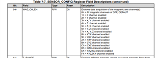
    By default each sensing axis is disabled and you must select which channels you are interested in using before the device will perform conversions:

    Are you programming this register somewhere in your code?

    Thanks,

    Scott

  • Hi Scott,  

    I forget add that API we call before putting it to  sleep mode. Which configures the Z channel "SENSOR_CONFIG_MAG_CH_EN_Z" to SENSOR CONFIG Register  

    appSensorErrCode_E appSensorPwrUpDefaultConfig(void)
    {
        int8_t retVal;
        retVal = initHallSensorDrv(); // Initializes the SPI driver 
        retVal = TMAG5170startup();   //  Implement the power of delay 
    
        data = (SENSOR_CONFIG_DEFAULT | SENSOR_CONFIG_X_RANGE_100mT
                | SENSOR_CONFIG_Y_RANGE_100mT | SENSOR_CONFIG_Z_RANGE_100mT
                | SENSOR_CONFIG_MAG_CH_EN_Z | SENSOR_CONFIG_SLEEPTIME_20ms);
    
        retVal = writeToRegister(SENSOR_CONFIG_ADDRESS, data);
        data = (DEVICE_CONFIG_DEFAULT
                    | DEVICE_CONFIG_OPERATING_MODE_ActiveMeasureMode
                    | DEVICE_CONFIG_MAG_TEMPCO_012C
                    | DEVICE_CONFIG_CONV_AVG_NUM_4x333Kbps10Kbps1axis);
         retVal = writeToRegister(DEVICE_CONFIG_ADDRESS, data);
        return appRetVal;
    }

    We are able to get the data without putting the sensor in sleep mode. 

    I am able  put the sensor in magnetic switch mode and in  autowake up configuration (DEVICE_CONFIG_OPERATING_MODE_WakeupandSleepMode) with mag threshold set on Z axis. I am able to get alert interrupt, after that i am able to put the sensor in active measure mode and then able to get the sensor data in active measure mode. I could also be able to switch between the Active measurement mode and autowakeup mode ( acting as mag switch) . Please note I am getting data by sending SPI command  for conversion trigger the get new sensor data. 

    I  hope as per the data sheet , in sleep  mode , SPI communication are allowed and hence the i expected a new data conversion. 

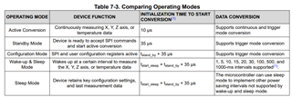
    Also I would like to understand what does "The microcontroller can use sleep mode to implement other power saving intervals not supported by wake-up and sleep mode." statement means  for sleep  mode 

    Thanks

    Ilan  

  • Ilan,

    Wake and Sleep mode will periodically cause the device to wake from sleep, initiate a conversion, and then return to sleep.  The frequency of this will occur based on SLEEPTIME in the SENSOR_CONFIG register.  If the SLEEPTIME interval does not meet the need of the system, it is possible to schedule the MCU to manually set the device for sleep mode for a preferred time period, wake the device and trigger a conversion.  After the conversion completes then the output registers should update and then the device can return to sleep until the next conversion is scheduled.

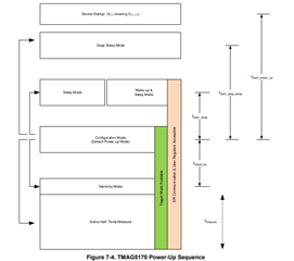
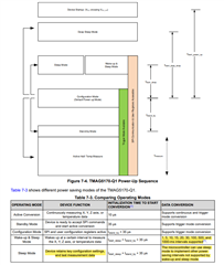
    While in sleep mode the device only retains register data, but functionally all blocks are otherwise disabled.  The ALRT pin or SPI communication are required to wake the device.  When waking from sleep mode there is a time period tstart_sleep which is required for the device to wake, after which the device should be in Configuration mode.

    Once in configuration mode, you should be able to trigger a conversion and capture data.  Perhaps in your case you are attempting to start a conversion before the device has returned from sleep mode, and therefore cannot perform a new conversion yet.  Can you check the timing to ensure that the device has had enough time to fully wake?

    Thanks,

    Scott

  • Hi Scott, 

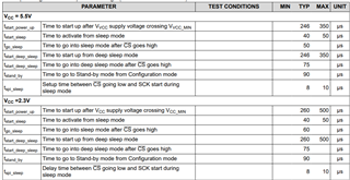
    I checked the t_start_sleep time it is mentioned in datasheet has 50 usec . Measured in hardware is 58 to 60 microseconds. I think more delay than minimum is fine. Also, as per the sleep transition diagram mentioned in the datasheet, I need to switch to configuration mode and then only can be able to change to other sleep modes or measure mode, is my understanding correct. 

    Similarly, while exiting from sleep it needs delay of  140 usec ( t_start_sleep + t_stand_by (datasheet pg. 10)) but we are around 149 usec. Do we need to include t_measure timing also here ? 


    I do not know, just before exiting sleep mode, If I do SPI register read to any register, then call  

    exitSleepMode() API, I could read the updated data. 

    <code> 

    /* SPI read to wake-up the sensor from sleep */
    retVal = normalReadRegister(DEVICE_CONFIG_ADDRESS,&input);
    retVal = exitSleepMode();

    </code> 

    With Regards

    Ilan T 

  • Ilan,

    When in sleep mode, SPI communication should cause the device to exit sleep mode and return to configuration mode. During standard sleep mode register data is retained, so I believe you should be able to read the last stored value at wakeup.

    For timing, you are correct, the sequence follows this pattern:

    The device should be able to start conversions following this timing

    tstart_sleep = 50 us

    tstandby = 90 us 

    With the equation in table 7-3, we should be ready within 175 us.