This thread has been locked.

If you have a related question, please click the "Ask a related question" button in the top right corner. The newly created question will be automatically linked to this question.

OPT3101: Questions about de-alias

Part Number: OPT3101

Hi,

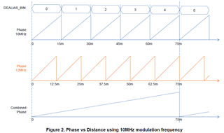
I'm trying to implement de-alias. As recommanded in https://e2e.ti.com/support/sensors-group/sensors/f/sensors-forum/891035/faq-opt3101-dealias-operation, I use the 8.57 MHz frequency.

At the OPT initialization, I initialize the registers like this:

typedef struct
{
    uint8_t registerAddress;
    uint16_t eepromAddress;
    uint32_t value;
} initValues_s;

const initValues_s registerToEeprom[NB_OF_INIT_REGISTERS] =
{
    /* EN_TEMP_CONV = enabled */
    {EN_TEMP_CONV, 0x03, 0xA0000},
    /* OVERRIDE_CLKGEN_REG = 0, CLIP_MODE_OFFSET = wrap around, CLIP_MODE_TEMP = wrap around, CLIP_MODE_NL = wrap around, CLIP_MODE_FC = clip */
    {CLIP_MODE_FC, 0x07, 0x200101},
    /* XTALK_FILT_TIME_CONST = 4 (tau = 16), IQ_READ_DATA_SEL = raw I/Q, USE_XTALK_REG_ILLUM = calibration value, USE_XTALK_FILT_ILLUM = filter, USE_XTALK_REG_INT = register value, USE_XTALK_FILT_INT = filter, INT_XTALK_CALIB = 0, DIS_AUTO_SCALE = enabled, FORCE_SCALE_VAL = 0 (digital scale = 64) */
    {FORCE_SCALE_VAL, 0x0B, 0x4002E0},
    /* IAMB_MAX_SEL = 11 (= 50 uA) */
    {IAMB_MAX_SEL, 0x0F, 0xB0},
    /* GPIO2_IBUF_EN = enabled, GPIO2_OBUF_EN = enabled, GPIO1_OBUF_EN = enabled, GPO2_MUX_SEL = DVSS, GPO1_MUX_SEL = DIG_GPO_0, GPO3_MUX_SEL = DVSS */
    {GPIO_REGISTER, 0x2F, 0x19080},
    /* PDN_GLOBAL = active, DIS_GLB_PD_I2CHOST = enabled, DIS_GLB_PD_OSC = disabled, DIS_GLB_PD_AMB_ADC = disabled, DIS_GLB_PD_AMB_DAC = disabled, DIS_GLB_PD_AFE_DAC = enabled, DIS_GLB_PD_AFE = enabled, DIS_GLB_PD_ILLUM_DRV = enabled, DIS_GLB_PD_TEMP_SENS = enabled, DIS_GLB_PD_REFSYS = disabled */
    {GLOBAL_POWER, 0x37, 0x161},
    /* NUM_AVG_SUB_FRAMES = 63, NUM_SUB_FRAMES = 63 */
    {NUM_AVG_SUB_FRAMES, 0x3F, 0x3F03F},
    /* TG_SEQ_INT_START = 9850 */
    {TG_SEQ_INT_START, 0x43, 0x267A},
    /* TG_SEQ_INT_END = 9858 */
    {TG_SEQ_INT_END, 0xB3, 0x2682},
    /* TG_SEQ_INT_MASK_END = 63 */
    {TG_SEQ_INT_MASK, 0x47, 0x03F03F},
    /* ILLUM_SCALE_H_TX0 = 1.4 mA, ILLUM_SCALE_L_TX0 = 1.4 mA, HDR_THR_HIGH = 65535 */
    {ILLUM_SCALE_H_TX0, 0x4B, 0x1BFFFF},
    /* HDR_THR_LOW = 0 */
    {HDR_THR_LOW, 0x4F, 0x0},
    /* ILLUM_DAC_H_TX0 = 15, ILLUM_DAC_L_TX0 = 13 */
    {ILLUM_DAC_H_TX0, 0x53, 0x1ED},
    /* MUX_SEL_COMPIN = PHASE_OUT is used for comparator input register */
    {MUX_SEL_COMPIN, 0x5B, 0x3},
    /* EN_FREQ_CORR = enabled, EN_FLOOP = enabled, EN_AUTO_FREQ_COUNT = measured value, SYS_CLK_DIVIDER = 10, START_FREQ_CALIB = 1, REF_COUNT_LIMIT = 19531 */
    {EN_FREQ_CORR, 0x63, 0xF54C4B},
    /* EN_CONT_FCALIB = frequency continuously measured */
    {EN_CONT_FCALIB, 0x67, 0x8000},
    /* PHASE_OFFSET_HDR1_TX0 = 7497 */
    {PHASE_OFFSET_HDR1_TX0, 0x105, 0x1D49},
    /* SCALE_PHASE_TEMP_COEFF = 2, EN_TEMP_CORR = disabled, EN_PHASE_CORR = enabled */
    {EN_TEMP_CORR, 0x93, 0x81},
    /* MONOSHOT_FZ_CLKCNT = 9900, MONOSHOT_NUMFRAME = 6, MONOSHOT_MODE = continuous mode */
    {MONOSHOT_MODE, 0x9B, 0x26AC18},
    /* SEL_HDR_MODE = ILLUM_DAC_H,  EN_ADAPTIVE_HDR = disabled, TX_SEQ_REG = 0-0-0-0-0-0, SEL_TX_CH = TX0, EN_TX_SWITCH = disabled */
    {EN_ADAPTIVE_HDR, 0x9F, 0xF90000},
    /* TG_ILLUMEN_START = 0*7/6 */
    {TG_ILLUMEN_START, 0xB7, 0x0},
    /* TG_ILLUMEN_END = 8500*7/6 */
    {TG_ILLUMEN_END, 0xBB, 0x26BC},
    /* TG_CAPTURE_START = 9300*7/6 */
    {TG_CAPTURE_START, 0xBF, 0x2A62},
    /* TG_CAPTURE_END = 9800*7/6 */
    {TG_CAPTURE_END, 0xC3, 0x2CA9},
    /* TG_CALC_START = 8500*7/6 */
    {TG_CALC_START, 0xC7, 0x26BC},
    /* TG_CALC_END = 9999*7/6 */
    {TG_CALC_END, 0xCB, 0x2D91},
    /* CAPTURE_CLK_CNT = 8600*7/6 */
    {CAPTURE_CLK_CNT, 0xCF, 0x2731},
    /* SUB_VD_CLK_CNT = 9999*7/6, TG_EN = disabled */
    {TG_EN, 0x97, 0x5B22},
};

Then, at the end of the initialization, I activate the sequencer like this:

/* Sequencer commands */
I2cOptSendValue(SEQUENCER_COMMAND_0_1, 0x122100);
I2cOptSendValue(SEQUENCER_COMMAND_2_3, 0x400);

/* Second modulation frequency settings */
I2cOptSendValue(NCR_CONFIG, 0x400001);
I2cOptSendValue(AMB_PHASE_CORR_PWL, 0x0);

/* Sequencer enable */
I2cOptSendValue(TG_EN, 0x5B22);
I2cOptSendValue(DIS_INTERRUPT, 0x30000);
I2cOptSendValue(TG_EN, 0x5B23);

1) I obtain two phases that alternate (I displayed them on the sensor's screen), which I presume is normal because we have two frequencies. Is that right?

2) The calibration cannot be done correctly. The crosstalk is too high (around 120-130) and the phase, which is supposed to be around 1749 at a distance of 400 mm at modulation frequency of 10 MHz, is way too high too (8xxx). But sometimes, it is an acceptable value (around 18xx). Why do I obtain these results?

3) During the crosstalk calibration, I display the crosstalk scale, iPhase, qPhase for both frequencies + alpha1 & beta1 (we only use them as we don't perform internal crosstalk calibration). Sometimes, all of them are null, and sometimes they aren't. Why? Moreover, in the de-alias documentation it's written that alpha & beta are comprised between -32 and 31, but I sometimes obtain a value of 48... How is that possible?

4) When I have an acceptable calibration (that is to say, crosstalk to 0 (though I think it is suspect) & phase offset in 18xx), The distance with the equations (3) and (4) of the de-alias document is way too high: more than ten meters instead of 400 mm. But when I replace the equation (3) with the following one, I get something more interesting: 1150 mm instead of 400 mm.

uint64_t Opt3101CalculateDealiasedPhase(uint8_t dealiasBin, uint16_t freq, uint8_t overflow, uint16_t phase)
{
    // return 4uLL*(uint64_t)((uint16_t)dealiasBin*freq) + ((uint64_t)overflow << 16) + (uint64_t)phase;
    return (uint64_t)(dealiasBin * (1 << 16)) + (uint64_t)phase;
}

How is that possible? Is the equation (3) wrong?

Thanks in advance for your answers.

  • Other weird notice:

    5) When I displayed the two phases that alternated, one was changing with the distance, but not the other. How is that possible?

  • Megn,

      Let me look into this. I will get back to you asap.

  • I just measured the crosstalk scale, iPhase, qPhase for both the frequencies (10 MHz and 8.57 MHz), plus alpha, beta, the crosstalk and the phase offset, for two of our products.

    Here are the results:

    Product n°14 10 MHz 8.57 MHz
    xtalk scale 0 0 0 3 0 0 0 0 4 0
    iPhase 931 115 935 650 114 975 119 929 651 116
    qPhase 245 275 263 168 281 246 280 261 169 279
    alpha 16 16 0 16 0
    beta 0 0 0 0 0
    xtalk 73 75 101 852 86
    phase 1710 1707 1695 9213 8712
    distance (mm) around 1200
    Product n°2* 10 MHz 8.57 MHz
    xtalk scale 0 0 0 0 0 0 0 0 0 0
    iPhase 454 167 152 121 997 167 167 888 117 309
    qPhase 167 573 413 155 167 167 275 889 150 167
    alpha 16 48 32 0 48

    beta

    32 0 48 16 0
    xtalk 265 96 1023 1023 165
    phase 1637 1860 1589 >= 9999 1648
    distance (mm) ~1200 keeps changing keeps changing keeps changing keeps changing

    I see no coherence between each result. How is it possible that the results are such different from one measure to one another? FYI, I didn't reflash the program between the measures, and I'm sure the program is the same on the two products.

    I derivated the formula given in the de-alias documentation, it gives me the following formulas for alpha & beta:

    int32_t alpha1 = 0, beta1 = 0;
    
    if((iPhase10 != 0) || (qPhase10 != 0))
    {
        alpha1 += iPhase10*iPhase12;
        alpha1 += qPhase10*qPhase12;
        alpha1 /= (iPhase10*iPhase10 + qPhase10*qPhase10);
        alpha1 <<= 4; /* x16 */
        alpha1 &= 0x3F;
    
        beta1 += iPhase10*qPhase12;
        beta1 -= qPhase10*iPhase12;
        beta1 /= (iPhase10*iPhase10 + qPhase10*qPhase10);
        beta1 <<= 4; /* x16 */
        beta1 &= 0x3F;
    }

    Is it correct?

    The formulas I've used to calculate the distance this time are the given formulas (3) and (4) of the de-alias doc.

    I precise that I'm always at a distance of 400 mm (so the theoretical phase is 1749). I also just tried to invert the location of the multiplication with the division, but it changed nothing.

  • Megan,

      I am not familiar with the de-alias ability in this part. I will have to read up on it myself.

    Here is a link to and E2E where one of our team members addressed this issue. Please read it and see if it helps you with your issue. I will attempt to address it on my side as well.

    https://e2e.ti.com/support/sensors-group/sensors/f/sensors-forum/1071173/opt3101-using-dealias-mode?tisearch=e2e-sitesearch&keymatch=opt3101%252520dealias#

  • Hi Gordon,

    Thanks for the link. Unfortunately, I have already applied the solution (it was in my link in the first post), but it does not work.

  • Megn,

      I will submit this to the designers and see what they have to say.

  • Megan,

      The designers said to check your code and register setting that it does work based on the example provided. I have asked for more information and or details. As soon as they get back to me I will let you knowwhat they provide.

    Let me know if you find anything in the code.

  • Megan,

      They did provide me with a fundamental understanding. Also take a look at this document. 5340.OPT3101-Dealiasing.pdf

    The basics as explained to me is that the OPT3101 doesnt have register locations for the XTALK and calibration for 2 frequencies. You have to go through the entire process for 10Mhz, and then again for 8.75Mhz saveing the data for both. Then load the 10Mhz data by default, and use the 8.75Mhz data to calculate the Alpha and Beta values. This will create the ability to shift to the 8.75Mhz without changing the registers. By shifting between the two frequencies it is possible to look out to very far distances and determine the approximate range to clculate the phas angle in. Only one of the frequency shifts will align showing this distance. 

    Hopefully this helps. I will close this for now, just reply if you still have problems. 

  • Hi Gordon,

    I have already looked at the document you provide, I have linked it in my first post. 

    I have another question:

    1) What is the difference between NCR_CONFIG (reg 0x40) and DEALIAS_FREQ (reg 0x71)?

    2) What is the difference between EN_DEALIAS_MEAS (reg 0x40) and DEALIAS_EN (reg 0x71)?

    I cannot understand which bit I should set in which circumstances, or if I have to set them all.

    Thanks in advance.

  • Megan,

      Register 0x71 is typically only used for debug and some testing. The statement: Select modulation frequency when DEALIAS_EN = 1. This register works
    only when OVERRIDE_CLKGEN_REG = 1. says that this register is only used for and when overiding clkgen. 

    Register 0x40 is the register that you will use. It can't hurt to set DEALIAS_FREQ, but it will not be used.

    What I do know is that you will want to use the 8.75Mhz not 12Mhz as it will cause noise that can't be corrected. This is something we discovered a while back. It will work, but it will be noisy and less accurate. The good news is that it looks like you are using 8.75Mhz.

    I have passed all of your comments to the design group. The only feedback so far is that it should be working. Obviouly its not so I will ask them to look again and see if they can find a problem or offer some help. 

    I have setup a system on my bench and I am trying to reproduce your problem. Any other information you can provide would be helpfull.