This thread has been locked.

If you have a related question, please click the "Ask a related question" button in the top right corner. The newly created question will be automatically linked to this question.

PGA305EVM-034: PGA305EVM SETUP

Part Number: PGA305EVM-034

I have PGA305EVM-034.

This is my first time with this system.

I am trying to setup a gain.

PGA305EVM-034 is setup for:

1. Voltage output

2. OWI

3. P_GAIN = 5

4. P_INV = NO

5. V_BRG = 2.5V

6. External Bridge 4.89K, $4.99K, 4.99K & 4.99K

==> Reading P_ADC = FFFEB1A

Changing only 

P_INV = YES

==> Reading P_ADC = FFFEAF0

Both reading are negative number.

If I changed gain polarity, should the reading change sign?

Question:

How do I calculate PADC digital reading from Bridge Values and Setting of the system (P_GAIN, P_INV, V_BRG)

Did Change Bridge values correctly by entering new Potentiometer value?

Thank you for your help.

Regards,

Igor 

  • Hi Igor,

    To be totally honest, I have not had that good of success using the demo bridge.  Part of the reason is that it is not a real pressure sensor.  So it really only shows that for a particular resistance setting you get a particular code outcome and you need to consider all of the options for full-scale range and gain settings.  So I prefer to use a bridge simulator as opposed to the adjusting the digital pot as the simulator is easier to change and more reliable with respect to consistency.

    That said, there can be some differences between each bridge resistance which can be seen as a negative or positive offset.  There could also be some offset related to the ADC itself.  I am confused by the results as I would expect that the result would be positive as INP+ would be 2.5V*(4.99/(4.99+4.89) = 1.26V, and IN- would be 1.25V, so the measurement with a gain of 1 would be 10mV positive.  The code values you are seeing at 24-bit level are quite close to 0 with perhaps some noise.  Even at a gain of 1, you could expect codes at around 33k.  So I suspect that either something is wrong with the setup or the measurement path.  You may want to use an accurate voltmeter across the inputs to see if you are getting around 10mV.

    The code results you are showing appear to be negative values, but you are perhaps missing something as you are showing values at 30 bits.  Have you tried making the potentiometer so that the input is 0V and then read back the value to determine the ADC offset?

    You can't tell the response of the system by a single reading, so you will need to exercise the potentiometer for low, mid and high values.  I would not suggest using the P_INV.  V_BRG is the bridge supply so you would want to use 2.5V for best resolution.  There are two gains.  One is the ADC PGA gain which is amplifier gain. The other gain is digital gain.  The goal is to set the ADC PGA gain (register setting) as high as you can to capture using the best dynamic range for your input and keep the digital gain (P_GAIN) equal to 1.

    This is why I like using a simulator, where I can know what I'm inputting as I change the input, that I can see immediately what code values are being returned for comparison.

    Best regards,

    Bob B

  • Hello Bob,


    Thank you for your response.


    I did try different values and P_INV to see if code changes from positive to negative è and it did not.


    I agree with you about the Bridge, it may not properly work.


    It may be because not digital potentiates work properly when its low side is not at ground potential è In PGA305EVM it is the upper leg Blush.


    My calculations showed same results as you had, only I used P_GAIN of 5, that was lowest evaluable option from pull down menu (see figure 1 below).


    I can setup an External Bridge with precision resistors è Please tell how to connect è Jumpers, wiring ,etc.


    How do I setup ADC PGA gain, and what would be a good value?


    Thank you for your help.


    Regards,

    Igor

  • Hi Igor,

    I made a mistake before as it relates to the PGA gain.  Sometimes my memory isn't as good as I would like it to be.  The P_Gain setting is the ADC PGA gain and the minimum is 5.  The digital gain setting relates to the EEPROM calibration value.

    What makes this so difficult is when using some made up bridge configuration you have to determine what you want the outcome to be.  I would suggest getting ahold of a simulation tool and creating a bridge circuit with values you want to use.  Determine the range of outputs and set the gain so that the output is at or near your largest bridge output as you are approaching full-scale.

    As to connecting the bridge to the EVM, I would suggest taking a look at the schematic at the end of the EVM user's guide for the appropriate connections.

    Best regards,

    Bob B 

  • Good afternoon Bob,


    Thank you for your input.


    I have CADANCE/OrCAD package, will get it simulated for 3 points, should be difficult.


    On EVM schematic I saw J1, J2 & J3 jumpers.  


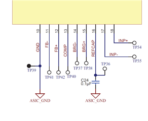
    I do not see how to connect to BRG- (is there a good point for clean analog groans on EVM board (see figure 1 below)?


    Regards,

    Igor

    FIGURE 1

    (attachment in my email to you)

  • Hi Igor,

    Note that the PGA305EVM has testpoint connections to the BRG+ (TP38) and BRG- (TP37) connections.  BRG+ provides the 2.5V and BRG- has an internal connection to ground.

    Best regards,

    Bob B