AWR1843AOPEVM: About the Layout PROC106B

Part Number: AWR1843AOPEVM

Hello,

I have a question about the Layout of AWR1843AOPEVM (PROC106B). 

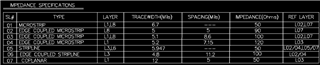
It is indicated "impedance specifications" about L1, L3, L6, L8 on the drawing of PROC106B. (Please see the image)

Which line do these impedance specs apply to?  

I think there are no lines that require impedance management. 

Please advise. 

Thanks and regards, 

Shoko 

  • Dear Shoko - 

    Thanks for the post and welcome to E2E. As the column label reads, L1, L3, L6 and L8 are layers of the PCB. This table is for the PCB fabricator to reference when making PCB stackup. This should match the materials being specified already, and is most useful in rare case any of the layers' material needs to be substituted. 

  • Hello Josh, 

    Thanks for your reply. 

    Yes, I already know the meaning and purpose of the table. 

    So, what I want to know is... 

    Is the wiring pattern used for AWR1843AOPEVM PCB adjusted to 50Ω, 100Ω, etc. (the impedance listed in this table)? 

    Please advise. 

    Thanks, Shoko 

  • Hello,

    The LVDS is routed as 100 ohm differential signal.

    The CAN is routed as 120 ohm differential signal.

    All other digital interfaces are routed as 50 ohm single ended signals.

    Regards,

    Adrian