This thread has been locked.

If you have a related question, please click the "Ask a related question" button in the top right corner. The newly created question will be automatically linked to this question.

AWR6843: EDMA transfer from ADCBuf to L1 - DSTBIDX question

Part Number: AWR6843

Dear TI Experts,

I am a bit confused by dstBIdx being set to zero in SDK DPU file rangeprocdsp.c.

In the rangeprocdsp.c source code file, located at <install_dir>\mmwave_sdk_03_06_00_00-LTS\packages\ti\datapath\dpu\rangeproc\src

Here is the code, starting at line 172:

syncACfg.aCount = dpParams->numAdcSamples * BYTES_PER_SAMP_1D;
syncACfg.bCount =MAX(dpParams->numRxAntennas / 2U, 1U) * dpParams->numChirpsPerChirpEvent;
syncACfg.srcBIdx = rangeProcObj->rxChanOffset * 2U ;
syncACfg.dstBIdx = 0U;

For 4 RX antennas, this works out to 

syncACfg.bCount = 2;

Does this mean that the second B array is overwriting the first B array in the destination buffer?

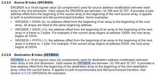
sprugs5b Keystone Architecture EDMA3 Controller gives an example of SRCBIDX being set to 0, and says on page 33, section 2.3.2.8, "SRCBIDX = 0000h (0): no address offset from the beginning of an array to the beginning of the next array. All arrays are fixed to the same beginning address." It goes on to say that the we should refer to the SRCBIDX examples for DSTBIDX.

Can you help me understand what it means that dstBIdx is set to zero?

Thank you for your help.

  • HI, there:

    Note that for syncA type of EDMA, a new event will be needed for every aCount.   Second, this input EDMA uses ping-pong buffer, and can change the source and destination address every time it is being triggered. So, it probably does not really mean anything that dstBIdx is set to zero.

    Please find more information at Doxygen documentation at file:///C:/ti/mmwave_sdk_03_06_00_00-LTS/packages/ti/datapath/dpu/rangeproc/docs/doxygen/html/dpu_rangedsp.html

    Please let me know what application you are working on with TI radar device. 

    Best,

    Zigang

  • This helped, thank you.

    It appears that dstBIdx set to zero does what you would expect: the destination address is not incremented between consecutive syncA transfers.
    The code in rangeprocdsp.c, in function DPU_RangeProcDSP_process shows this order of events:

    1. PING and PONG transfers are started
    2. PING is processed in the PING adcDataIn buffer in L1.
    3. PING transfer is started (relative to the first PING, this one's source address is incremented by srcBIdx = 2*numAdcSamples*sizeof(complex) - but its destination address is the same - the PING adcDataIn buffer in L1)
    4. PONG is processed in the PONG adcDataIn buffer in L1
    5. PONG transfer is started (again, relative to the first PONG, this one's source address is incremented by srcBIdx = 2*numAdcSamples*sizeof(complex) - but its destination address is the same - the PONG adcDataIn buffer in L1)
    6. The second PING is processed in the PING adcDataIn buffer in L1.
    7. The second PONG is processed in the PONG adcDataIn buffer in L1

    In the function rangeProcDSP_ConfigDataInEDMA in rangeprocdsp.c, PING was set to transfer antennas zero and two, and PONG was set to transfer antennas 1 and 3. This means that the PING/PONG order of execution in DPU_RangeProcDSP_process processes antenna zero, then antenna one, then antenna two, and finally antenna three.

  • Hi, there:

    So, the data process on the EDMA data destination will be finished before the next EDMA started.  That is why the target address can be the same. 

    Glad that you figure it out.  Let me know if we can close this thread. 

    Best,
    Zigang