This thread has been locked.

If you have a related question, please click the "Ask a related question" button in the top right corner. The newly created question will be automatically linked to this question.

OPT3101: The OPT3101 channel switch has a distance jump

Part Number: OPT3101


Hi Team:

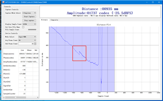
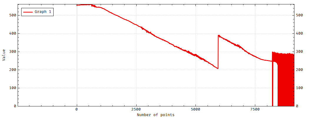
       The OPT3101 is set to SuperHDR mode. When the distance between the sensor and the target board is tested from far to near, the current channel switching will show a jump from the target distance to far, and it is relatively large;

        This is the configuration:


     This is the distance jump that occurs when I move the sensor, and the distance from far to near is not continuous when switching the current channel;

     How to solve this problem?

    Thanks!


  • Pengsheng,

      Based on the plot, labeled number of points, this looks like amplitude not distance. If this is distance and if this is the same system from another E2E, then it looks like you are getting better than 5m which is further than expected. The shift can be from the OPT3101 increasing the current due to the overall distance and that produces a larger error. I will need more information to understand what happening if this is not the same project. 

  • Gordon:

        This is distance;Test OPT3101EVM, the target is fixed, moving EVM from far to near, this phenomenon also occurs when the current channel is switched, but the distance jump is not very large,

        This is EVM data:


  • Pengsheng,

    This is an effect of using HDR. The current will change as neded to maintain the proper amplitude and phase based on the distance. The step should be minimal or non existant if the calibration is correct. If you see the step then you need to look closer at the calibration for HDR mode especily when doing the phase offset calibration. 

    Super HDR Mode calibration

     In HDR mode, the current can switch between 2 current settings on one TX channel, and with super-HDR, TX1 can be used to add 2 more current settings.

     What we think is going on here is that the phase offset measurements are not being done at the proper amplitude for each current setting.

     The documentation recommends doing phase offset calibration at a target distance where the amplitude is between 16000-24000. The preset values in the SDK are arbitrary and definitely don’t follow this rule. The values are set like below in OPT3101Coefficients.cpp.

     void environmentalController::manuallySetReferenceDistances(){

           this->refDistancesInMM[0][0]=50;

           this->refDistancesInMM[0][1]=120;

           this->refDistancesInMM[1][0]=60;

           this->refDistancesInMM[1][1]=150;

           this->refDistancesInMM[2][0]=0;

           this->refDistancesInMM[2][1]=0;

    }

     The indexing on refDistancesInMM is [Tx channel] and [current setting, 0 being H and 1 being L]. In order for them to find the proper distances to set for each current and tx setting, you will need to change your configuration to do just one current, flash that, and see at what distance you can get 16000-24000 codes for that particular current. At higher currents, that distance will be pretty far with a white background, so you can use darker backgrounds in order to get lower amplitude settings, but they’ll need to remember what current settings used what color background when you do the calibration.

     Once you know these distances, you can enter that into OPT3101Coefficients.cpp and then use super-HDR configuration and perform the calibration.

  • Gordon:

        I know that the set calibration distance is required by the amplitude, and I do so, but the test distance is far to close and there will be a jump in the distance, is there any other possible reason?]

        Thanks!


  • Pengsheng,

      I have asked if there was anything else to look or what you can do to fix it. I'm waiting for a response. Sorry it is taking so long. I will get back to you asap.

  • Gordon:

       The documentation recommends doing phase offset calibration at a target distance where the amplitude is between 16000-24000. The preset values in the SDK are arbitrary and definitely don’t follow this rule. The values are set like below in OPT3101Coefficients.cpp;

    void environmentalController::manuallySetReferenceDistances();The calibration distance is set in relation to the current of the channel, and the current correlation parameters are set in the OPT3101 Configurator Tool; I have four questioons:
       1: Mark 1 is to set the maximum current, SFH 4550 Forward current 100mA, SCALE H TX1 is set to 100.8mA, right?
       2:What is the Max Ambient Current parameter set based on;
       3:Based on what is the SuperHDR Ratio parameter set;
       4:How to select the value of H Threshold;
     
       Thanks!
  • Pengsheng,

      When doing the calibration process, you will have 4 currents, these 4 currents will have a distance that you will determine based on achieving an amplitude of between 16000-24000. You will need to addjust your currents to find one of the current setting that will put the distance and ambient at or very close to where you are seeing the step or jump in distance. This jump is normal as the currents change for the Auto HDR mode in order to achive greater sensitivity and accuracy. Calibrating based on currents and distance to remove the shift will correct the shift at this distance. It may show up at a different distance usually much further or much closer. I will get into more of this and how to do it based on your last question.

  • Pengsheng,

      1) The max current of the emitter is 100mA. However the OPT3101 is first off a 10Mhz signal so it is not always on or off. It actually has a duty cycle, The duty cycle is based on "Duty Cycle = (NUM_AVG_SUB_FRAMES + 1) / (NUM_SUB_FRAMES + 1)" If the duty cucly is 50% then the OPT3101 at full current of 173mA would be 86mA average, so the current will not exceed the 100mA max of the emitter. 

    2) 20uA is correct based on the corner frequency

    7.3.3 Ambient Cancellation
    The ambient cancellation circuit provides the dc and low-frequency diode current while biasing the diode at 1 V.
    Figure 22 shows the frequency response of the ambient cancellation circuit. A diode current with frequency
    below fc2 has second-order rejection. The corner frequency fc2 is designed to be at 50 kHz for IAMB_MAX_SEL =
    0 (20 μA ambient current support). Below frequency fc1 (approximately at 10 Hz), attenuation becomes first-order.
    So for a frequency of 1 kHz, the rejection would be (50 kHz / 1 kHz) × 2 = 2500 = 68 dB.

    3) I don't have the exact answer to this, except that it sets a ratio of the 4 currents. Super HDR is an extension of Auto HDR. In Auto HDR there is a setting for Auto HDR Scale. The ratio will impact the scale and the final currents. All of this is based on your entire distance range that you are trying to achieve. Example: If your distance range is 1m - 3m then you reduce the ratio because you don't need the ultra low currents. If you need 100mm to 3m then you will increase the ratio to to get the ultra low and the high currents. You can tweek this ratio to put one of the currents and distance for the calibration near the step that you see. 

    4) the H threshold is based on the amplitude level that you want it to switch currents. At each current when the amplitude reaches 26000 the current will increase to the next level. This can switch current earlier to minimize the step as well. Only you can determine this by testing your system.

    In the plot you can see that changing the current can create a potential step in distance. This is not always the case. Use the System estimator to look at the currents and expected operations, then use the System Configurator to get the currents. The two compliment each other so use them they will help you maximize the system. Then set the distances based on the currents and the amplitude. Put that into the CCS code and run your calibration. 

    Much of what you are asking is in using the tools. Good luck.