This thread has been locked.

If you have a related question, please click the "Ask a related question" button in the top right corner. The newly created question will be automatically linked to this question.

IWR6843ISK-ODS: Observed discrepancy in y & z value in ROS based pointcloud

Part Number: IWR6843ISK-ODS

Hi,

I am using IWR6843ISK-ODS in ros2 Ubuntu22.04LTS with small obstacle detection binary file for extrinsic radar-camera calibration. 
I am using a corner reflector placed at different positions and then checking the value of point from rviz2 using "Publish point" option.
In ROS, the coordinates are x :  forward +ve, y : left +ve, z : above +ve but I observed a discrepancy with the values I obtained during calibration. 
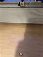
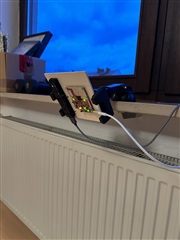
I have the setup in where sensors point to ground and corner reflector is placed on ground.

  
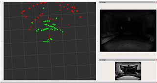
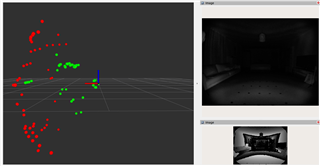
And the position of CR is as below along with the coordinates obtained from "Publish point" option:

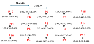
Here, all the adjacent points are separated by 0.25m in lateral direction. I have also mentioned the x,y,z points obtained from publish point in the image.
The difference between the y value of P12 and P15 shall be close to 1m but it's 0.5m whereas the difference of z value is close to 1m i.e. 0.992m. This is same for pairs P11&P14, P10&P13 and likewise for other points as well.

My cfg file has correct compRangeBiasAndRxChanPhase as per ODS antenna and repeated the process another time but got the same results.

Also, I have not made any changes to file DataHandlerClass.cpp under READ-OBJ_STRUCT.

Could you please tell on the basis of above data if the y & z values to be swapped? Has there been any such discrepancy in coordinate frame? 

Best regards,
Pushkar

  • Hi

    Thank you for your query, Please allow us a couple of days to respond

    Regards

  • Hello Pushkar,

    The coordinate system of ROS and the output of the Radar are different, for that reason DataHandlerClass has the following code.

    RScan->points[i].x = mmwData.newObjOut.y; // ROS standard coordinate system X-axis is forward which is the mmWave sensor Y-axis
    RScan->points[i].y = -mmwData.newObjOut.x; // ROS standard coordinate system Y-axis is left which is the mmWave sensor -(X-axis)
    RScan->points[i].z = mmwData.newObjOut.z; // ROS standard coordinate system Z-axis is up which is the same as mmWave sensor Z-axis

    For ODS you need to change more than compRangeBiasAndRxChanPhase.

    If you are using a 3D People Tracking based binary which has the Capon algorithm chain, you need to ensure the following commands are in place in the configuration file being used to set the ODS antenna geometry.

    antGeometry0 0 0 -1 -1 -2 -2 -3 -3 -2 -2 -3 -3
    antGeometry1 0 -1 -1 0 0 -1 -1 0 -2 -3 -3 -2
    antPhaseRot 1 -1 -1 1 1 -1 -1 1 1 -1 -1 1

    If you are using an Out of Box demo binary (which Small Obstacle Detection of the ROS driver is based on), then the binary needs to be recompiled with a different antenna_geometry.c and main.c file that overwrites the default ones. This can be found in C:\ti\<RADAR_TOOBOX_DIR>\source\ti\examples\Out_Of_Box_Demo\src\xwr6843ODS.

    Note in all our documentation that ISK and ISK-ODS are two different antenna patterns and are not cross compatible immediately. I would recommend for ease of use with the ODS EVM to not use the Small Obstacle Detection binary, and stick with 3D People Tracking one which is more configurable and newer.

    Best Regards,

    Pedrhom

  • Hi Pedrhom,

    Thank you for detailed explanation. 

    I understood now that for ODS I need to make changes in antenna geometry and main.c file which i can get it from <RADAR_TOOBOX_DIR>\source\ti\examples\Out_Of_Box_Demo\src\xwr6843ODS.

    These changes shall be done irrespective of binary file used i.e. small obstacle detection or 3D people tracking or is it only for small obstacle detection and for 3D people tracking binary the ODS antenna configuration is done with  antGeometry0, antGeometry1 & antPhaseRot parameters alone? Please give me a clarity on this. 

    I want to use small obstacle detection with static scene enabled for calibration with camera as it outputs less number of points to easily distinguish points from corner reflector. If I use 3D people tracking with static scene enabled there are a lot of points already and calibration process becomes pretty difficult. 
    For test data capturing after calibration, I will use 3D people tracking binary as it gives more points than small obstacle binary. 

    To make the changes you mentioned firstly for antenna geometry, I should copy the ODS geomtery which is 

    ANTDEF_AntGeometry gAntDef_IWR6843ODS = {    .txAnt = { { 0, 0 }, { 2, 0 }, { 2, 2 } },     .rxAnt = { { 0, 0 }, { 0, 1 }, { 1, 1 }, { 1, 0 } } };

    and replace the tx and rx values with ANTDEF_AntGeometry gAntDef_default under antenna_geometry file located in "ti/mmwave_sdk_03_06_02_00-LTS/packages/ti/board/" in my ubuntu machine. 
    Is this correct?

    Second, could you guide on main.c file from <RADAR_TOOBOX_DIR>\source\ti\examples\Out_Of_Box_Demo\src\xwr6843ODS shall be replaced where? I didn't find any main.c file under mmwave_ros_pkg. There are multiple main.c files under "ti/mmwave_sdk_03_06_02_00-LTS/packages/ti/drivers" .

    Therefore, after antenna geometry and main.c file I shall build the mmwave_ros_pkg again. Could you please confirm if this is correct?

    Best regards,
    Pushkar
  • Hello Pushkar,

    If using 3D People Tracking binary then no changes are needed outside of the antGeometry0, antGeometry1 & antPhaseRot parameters within the configuration file you are using.

    When tuned properly, the Capon chain (3D People Tracking) will detect static points better and more clearly than the Bartlett one (OOB/Small Obstacle Detection). For your convenience I have attached two configurations to use with the 3D People Tracking demo with good static detection. You will need to replace the antGeometry values as I made them originally for 6843AOP.

    For small obstacle detection, you'd have to change the source code of the binary that is flashed to the device, not the ROS driver source code. This is done via Code Composer Studio, where you import the project of choice, make changes, then compile it to create the .bin file that is to be flashed. I again recommend staying with 3DPT and tuning/playing with parameters

    Best Regards,

    Pedrhom

    3DPC_Based_CFG_Static.cfg

    Overhead_Static_6843AOP_3meters.cfg

  • Hi Pedrhom,

    Thank you so much for providing the cfg files. It will be a good start and can make changes as per my use case. 
    I will stick to 3DPT and fine-tune the parameters, thanks a lot for your guidance. 

    I will test the cfg files and get back to you.

    Best regards,
    Pushkar

  • Hi Pedrhom,

    I achieved range resolution of 5.2 cm with below parameters and refined the angular resolution as well. But still the point cloud is sparse.

    I would like to know if there is a possibility to increase the density of the point cloud based on parameters in cfg file? Since in my use case inside vehicle cabin the distance between driver and radar is within 0.4-0.8 meters and there are only a few points observed.

    I am currently using the below parameters:

    sensorStop
    flushCfg
    dfeDataOutputMode 1
    channelCfg 15 7 0
    adcCfg 2 1
    adcbufCfg -1 0 1 1 1
    
    profileCfg 0 60.5 10 8 53 131586 0 66 1 128 3000 2 1 36
    chirpCfg 0 0 0 0 0 0 0 1
    chirpCfg 1 1 0 0 0 0 0 2
    chirpCfg 2 2 0 0 0 0 0 4
    frameCfg 0 2 64 0 200.00 1 0
    
    dynamicRACfarCfg -1 4 85 2 2 8 12 4 4 20.00 20.00 0.40 1 1
    staticRACfarCfg -1 4 85 2 2 8 8 4 4 20.00 20.00 0.30 0 0
    dynamicRangeAngleCfg -1 0.75 0.0010 1 0
    dynamic2DAngleCfg -1 1 0.0300 1 0 1 0.30 0.85 8.00
    staticRangeAngleCfg -1 1 8 8
    antGeometry0 0 0 -1 -1 -2 -2 -3 -3 -2 -2 -3 -3
    antGeometry1 0 -1 -1 0 0 -1 -1 0 -2 -3 -3 -2
    antPhaseRot 1 -1 -1 1 1 -1 -1 1 1 -1 -1 1
    fovCfg -1 45.0 45.0
    compRangeBiasAndRxChanPhase 0 1 0 1 0 1 0 1 0 1 0 1 0 1 0 1 0 1 0 1 0 1 0 1 0
    
    staticBoundaryBox -2 2 0.3 3.5 0 2
    boundaryBox -2 2 0.3 6.0 0 2
    sensorPosition 0.3 0 0
    gatingParam 2 2 2 2 4
    stateParam 5 3 12 50 5 50
    allocationParam 20 35 0.1 10 0.6 20
    maxAcceleration 1 1 1
    trackingCfg 1 2 800 30 46 96 100
    presenceBoundaryBox -2 2 0.3 6.0 0 2
    sensorStart
    

    Thank you and best regards,
    Pushkar

  • Hello Pushkar,

    CFAR thresholds of 20 can be pretty high. I would reduce those, and if you start over detecting and seeing a bunch of noise, you should increase TX power backoff due to the very short distances you are working with.

    Best Regards,

    Pedrhom

  • Hi Pedrhom,

    I tried your suggestion and the number of points decreased with increase in Tx power backoff but still has a lot of points in the static scene. In the right side you can see the pic from the ToF camera and there are no objects in the bore-sight or around it. I assume they are ghost targets and checked in another room and still the same. This is with static scene enabled. Also, even with <angleThre> of 30 or more, I get rainbow like pointcloud. Is this still too less? 


    Further, when I use a corner reflector and move it around in this setup (static scene enabled), then the point cloud move along with the corner reflector. But as soon as I make the corner reflector static or place it on something, the point cloud of corner reflector goes away and because of this i find it very difficult to perform extrinsic calibration. I have been trying different surroundings and playing with multiple parameters for a long time now but no success.

    This is with using 3D people detection binary. 

    Could you suggest how to resolve this so many static points and why the points are going away from corner reflector when made static? 

    Thank you.
    Best regards,
    Pushkar

  • Hello Pushkar,

    This is mostly expected behavior. With static detections enabled, you are going to see the floor, the walls, the ceiling, etc. Not just static objects. If you set the sensorPosition value to the proper height, you should be able to then just remove any point with a Z (elevation) value that is negative as that can be deemed below the floor. These points could be generated by several different things such as multipath reflections, but it is noise nevertheless. Try a really high angleThre like 50 and see what happens, the values only go up this high when doing this in static mode, but it is okay to do so. Worst case scenario if the value is too high you will see no points, this is all just post-processing filtering.

    The points right up against the sensor is due to antenna coupling. Think of this as the radar detecting itself. You can remove these points via dynamicRACfarCfg and staticRACfarCfg. Look for cfarDiscardLeftRange within the document below. This will remove the X amount of points closest to the sensor. Since with static detection on you will always detect some antenna coupling, it is safe to have a relatively high value for this (25 and higher is still okay, but should be tested).

    https://dev.ti.com/tirex/explore/node?node=A__AIQPG9x7K34A8l4ZELgznA__radar_toolbox__1AslXXD__LATEST

    This is the process with Radar: you detect, filter/process, check output, tune, repeat.

    Best Regards,

    Pedrhom