This thread has been locked.

If you have a related question, please click the "Ask a related question" button in the top right corner. The newly created question will be automatically linked to this question.

AWR6843AOP: "compRangeBiasAndRxChanPhase" setting problem

Part Number: AWR6843AOP
Other Parts Discussed in Thread: IWR6843AOP

Hi Ti,

I want to confirm some setting item in mmWave SDK user guide.


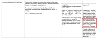
In " compRangeBiasAndRxChanPhase " we see the description in the red box in the figure below.
But we can't understand what he mean.


We will burn "xwr68xx_mmw_demo.bin" before executing mmWave visualizer.
Can we ignore the instructions in the red box?


Thanks,
Vincent

  • Hey Vincent,

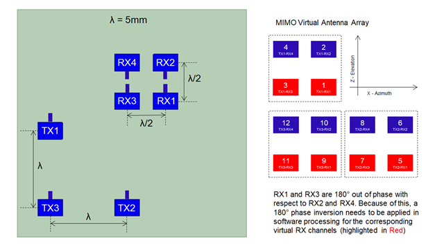
    You should not ignore the sign reversal of the phase compensation coefficients and should use the parameters below as a baseline for compensation. Due to the antenna layout of the xWR6843AOP, there will be some SNR degradation if the coefficients are not sign inverted. It won't be a major loss of accuracy or performance, but its better to use the inverted sign coefficients instead.

    compRangeBiasAndRxChanPhase 0.0 1 0 -1 0 1 0 -1 0 1 0 -1 0 1 0 -1 0 1 0 -1 0 1 0 -1 0

    Regards,
    Kristien
  • Hi Kristien,

    So What does "Note the sign reversal required for phase compensation coefficients in xwr6443 demo running on IWR6843AOP device." mean?
    We don't use xwr6443 demo on 6843AOP.

    So even we burned "xwr68xx_mmw_demo.bin" before executing mmWave visualizer.
    We still change our calibration baseline into "compRangeBiasAndRxChanPhase 0.0 1 0 -1 0 1 0 -1 0 1 0 -1 0 1 0 -1 0 1 0 -1 0 1 0 -1 0" ?


    Thanks,
    Vincent

  • Hey Vincent,

    As mentioned in the previous reply, the phase compensation sign inversion is needed because of the physical antenna layout, specifically the polarization of the xWR6843AOP. The SDK notes the xwr6443 demo, however this note should apply to any AOP demo because the polarization is inherent to the device and must be accounted for in software as mentioned in the antenna layout note below.

    In other words, this is likely an oversight in documentation and should be revised.

    Regards,

    Kristien

  • Hi Kristien,

    If I use" 0.0 1 0 1 0 1 0 1 0 1 0 1 0 1 0 1 0 1 0 1 0 1 0 1 0" as the basis.
    And I get the value like" 0.0636043 -0.10580 0.64191 -0.13910 -0.85986 -0.15384 0.76923 -0.36783 -0.41379 -0.27747 0.41409 0.31479 -0.42755 -0.31577 0.31247 0.07770 -0.53415 -0.09827 0.91251 -0.01834 -0.60550 -0.17191 0.61890 0.00000 -1.00000."

    You mentioned that the value needs to be reversed.
    Can I directly add a negative sign to it
    , such as "0.0636043 -0.10580 0.64191 0.13910 -0.85986 -0.15384 0.76923 0.36783 -0.41379 -0.27747 0.41409 -0.31479 -0.42755 -0.31577 0.31247 -0.07770 -0.53415 -0.09827 0.91251 0.01834 -0.60550 -0.17191 0.61890 0.00000 -1.00000."?

    Thanks,
    Vincent

  • Hey Vincent,

    You do not need to reverse the signs for recalibrated range bias and phase compensation parameters since the calibration process should account for the polarization of the xWR6843AOP along with any other imperfections in antenna layout, RF delays, and other manufacturing and real-world inconsistencies. 

    Regards,

    Kristien

  • Hi Kristien,

    So I can use "0.0636043 -0.10580 0.64191 -0.13910 -0.85986 -0.15384 0.76923 -0.36783 -0.41379 -0.27747 0.41409 0.31479 -0.42755 -0.31577 0.31247 0.07770 -0.53415 -0.09827 0.91251 -0.01834 -0.60550 -0.17191 0.61890 0.00000 -1.00000.".
    Even though I used " 0.0 1 0 1 0 1 0 1 0 1 0 1 0 1 0 1 0 1 0 1 0 1 0 1 0" as the base.
    As it stands, I don't need to invert any parameters because some of the error is already compensated for when I calibrate.

    Is my understanding correct?

    Thanks
    Vincent

  • Hey Vincent,

    Yes, that is correct. Any errors should be accounted for by the calibration process.

    Regards,

    Kristien

  • Hi Kristien,

    But this conclusion leaves us puzzled.
    If you can use "0.0 1 0 1 0 1 0 1 0 1 0 1 0 1 0 1 0 1 0 1 0 1 0 1 0" as the base to get the calibration value.

    Why does the document need to mark the "0.0 1 0 -1 0 1 0 -1 0 1 0 -1 0 1 0 -1 0 1 0 -1 0 1 0 -1 0" situation separately?

    Thanks,
    Vincent

  • Hey Vincent,

    The demo denotes these coefficients as an example or baseline of how to address the phase inversion of the antennas. Keep in mind that the inverted phase coefficients are not used in the calibration process as shown in the profile_calibration.cfg. Since there is no phase inversion used in the calibration process, any adjustments from the antennas phase inversion will be captured in the resulting coefficients from the calibration.

    Regards,

    Kristien