This thread has been locked.

If you have a related question, please click the "Ask a related question" button in the top right corner. The newly created question will be automatically linked to this question.

LDC1101: LDC Tools - Time Constant Calculations

Part Number: LDC1101

Hello, I am seeing Time Constant numbers from the LDC_Tools-ext51 spreadsheet that seem to be differing from the guideline given in the LDC1101 datasheet section 9.1.5, 9.1.6.

Constants used in the below calculations are as follows

Vamp = 0.6V ( specified in datasheet)

fsensormin = 4.03MHz (calculated in spreadsheet, agrees with real world measurement)

Rpmin = 750 ohms (set in spreadsheet based on my finding 1066 ohms real world Rp with maximum metal by VNA measurement)

Time constant 1 setting (refer to datasheet Section 9.1.5)

R1*C1=sqrt(2)/(pi*Vamp*fsensormin)
R1*C1=sqrt(2)/(pi*0.6*4e6) = 1.876e-7
Calculator chosen values are [R1C1]= 0xDE
R1=b1101 = 251k ohms; C1 = b11 = 6pF
R1*C1(programmed) = 1.5e-6

Since 1.876e-7 does not equal 1.5e-6, I'm not sure whether to trust the calculated number in my application.

Time constant 2 setting (refer to datasheet Section 9.1.6)

R2*C2=2*Rpmin*Csensor
R2*C2=2*750*130e-12 = 9.75e-8
Calculator chosen values are [R2C2]= 0x7E
R2=b111110 =43.26k ohms ; C2=b01 = 6pF
R2*C2 (programmed) = 2.6e-7

Since 9.75e-8 does not equal 2.6e-7, I'm not sure whether to trust the calculated number in my application.

Please also note that I think there is a typo in the datasheet, as it refers to TC1 being programmed in the 0x03 register, but it should be 0x02

R1 is the programmed setting for TC1.R1 (register 0x03-bits[4:0]), and
• C1 is the programmed setting for TC1.C1 (register 0x03-bits[7:6])
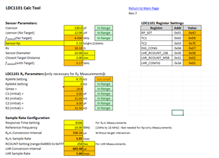
6646.LDC_Tools-ext51.xlsx

  • Correction

    R2*C2=2*750*130e-12 = 1.95e-7

    Still, 1.95e-7 does not equal 2.6e-7

  • Arthur,

    Thanks for the post and the detailed descriptions.

    I will review your findings and update the thread on Monday.

    Have a great weekend.

    Regards,
    John

  • Arthur,

    Would you please upload the a copy spreadsheet you are using with your data values entered?

    Regards,

    John

  • John,

    There is a link in my post above with the text "6646.LDC_Tools-ext51.xlsx", can you access that?

  • Arthur,

    I was able to access the link and download & open the spreadsheet. Thanks.
    I will review it and update the thread tomorrow.

    Regards,

    John

  • Arthur,

    I scanned some of the tool's calculations, and it looks oaky.
    There's a lot of conditional calculations, and that is what is causing the rounded results you are seeing.
    Please consider using the tool's results in your design.

    And many thanks for the heads-up on the TC1 register reference. 
    Looks like a copy-and-paste error.

    Regards,

    John

  • Hi John,

    Are you able to confirm that the spreadsheet is using the following datasheet equations to calculate the recommended time constant values?  Maybe as an insider you can see the calculation, but the formulas are hidden from my view.

    R1*C1=sqrt(2)/(pi*Vamp*fsensormin)

    R2*C2=2*Rpmin*Csensor

    Also, can you advise about the warning "too small" my spreadsheet is showing for the 750 ohm Rpmin setting?  Am I violating some design rule?  I did run an experiment on the VNA to check the measurable Rp values.  I got Rpmax (no metal) of 4.37k ohms and Rpmin (max metal) of 1.06k ohms.  So the 750 ohm Rpmin, 6k ohm Rpmax settings seem to pass that sanity check.

  • Arthur,

    The spreadsheet uses the equations given in the data sheet.
    It also does some rounding and calculations to account for parameter limits and the values of the TCx resistors and capacitors imposed by the register settings. 

    for the "too small" message, I think the solution will be driven by your requirements.
    The value does align with your data, but the tool is also considering some add'l device-related factors in the calculations.
    Section 9.1.4 of the data sheet gives some guidance on how to fix it. 
    The internal calculations imply raising the nominal sensor frequency (w/o target) will help, as section 9.1.4 advises, along with increasing Rpmin or Csensor.

    Regards,
    John

  • Hi John,

    Sorry, I think I made another mistake previously and now I think the spreadsheet time constant recommendation is totally reasonable.  I was reading out the bit order wrong when trying to determine the R1/C1 settings.

    R1 = sqrt(2)/(pi*0.6*4e6*6e-12) = 31.3k ohms

    I can achieve 33.9k ohms by using 1 less than the maximum R1 setting, that is b1'1110. 

    So R1 = 33.9k, C1 = 6pF, hex value is 0xDE

    R1*C1 (programmed) = 2.03e-7 is what the spreadsheet is recommending and closely aligned to 1.87e-7 ideal value.

    On the "too small" message, do you think that is being checked against datasheet section 9.1.4.4 ? In other words my device is not meeting the Qmin recommendation?  I am meeting the Qmax, and that's what's displayed in the spreadsheet (my value is 16.8).  But maybe the spreadsheet is checking Qmin in order to conclude that my Rpmin is too small? 

  • Arthur,

    I don't see the spreadsheet explicitly calculating Qmin. 
    It looks like the "too small" message results from an internal comparison between the time constant (Rpmin & Csensor), Fsensor and some voltages, which may ultimately be the same thing as minimum Q.

    Does this help?

    regards,
    John