Other Parts Discussed in Thread: AWR6843AOP
Hello,
I'm using AWR1843AOP in my project.
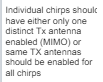
I have a couple of questions regarding why the tx antennas need to be sequentially opened in the chirpCfg parameters.
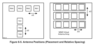
1- When I examined the mmwdemo_rfparser.c function, when the tx antennas are sequentially opened as 1-2-4 in the chirpCfg parameters, the numTxAntAzim value is assigned as 2 and the numTxAntElev value is assigned as 1, and accordingly, the numVirtualAntAzim value is calculated as 8 and the numVirtualAntElev value is calculated as 4. I couldn't understand whether the calculated value matches with the Tx antenna arrangement on the AWR1843AOP chip. Why does it take numTxAntAzim = 2 and numTxAntElev = 1?
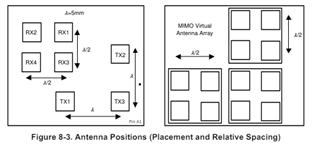
2- mmwdemo_rfparser.c is used in other demos for other chips as well, and when the tx antennas are sequentially opened as 1-2-4 in the chirpCfg parameters, the numTxAntAzim value is also 2 and the numTxAntElev value is 1 for AWR6843AOP chip. AWR6843AOP and AWR1843AOP have different hardware arrangements, so how is this possible? Is this correct?
Onur Emre