This thread has been locked.

If you have a related question, please click the "Ask a related question" button in the top right corner. The newly created question will be automatically linked to this question.

AWR6843ISK: mmwave sensing estimator tool version 2.4

Part Number: AWR6843ISK
Other Parts Discussed in Thread: TIDEP-01023, , AWR6843

hi,

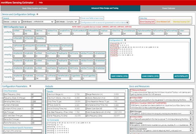
 with reference to "Design Guide: TIDEP-01023 Child-Presence and Occupant-Detection Reference Design Using 60-GHz Antenn on-Package mmWave Sensor", pleas refer page no:7(table 2.1)..i can enter only first 5 parameters using mmwave sensing estimator tool (version 2.4) under basic chirp design and creation(refer attached screenshot) and donot' have any option for user to chose other parameter like idle time ,adc_valid start time and all.

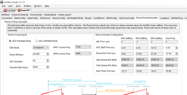
Question 1: please check and confirm, how did you calculate the remaining parameters available in the table 2.1 of reference design ?

we have checked the TI design example using AWR6843ISK evaluation kit by loading the .bin file from "radar_toolbox_1_30_01_03\source\ti\examples\InCabin_Sensing\AWR6843_CPD_with_Classification\prebuilt_binaries and

running the visualizer.ex on the PC from the folder "radar_toolbox_1_30_01_03\tools\visualizers\InCabin_CPD_w_Classification_GUI\AWR6843_CPD_w_Classification_visualizer.exe.

please refer chirp design parameters to be used are mentioned under folder "C:\ti\radar_toolbox_1_30_01_03\tools\visualizers\InCabin_CPD_w_Classification_GUI\config_file\vod_6843_isk_frontMount_2row.cfg"

profileCfg 0 60.00 2789 11 41 0 0 97.0 1 64 2200 0 0 36
profileCfg 1 60.00 20 11 41 0 0 97.0 1 64 2200 0 0 36
chirpCfg 0 0 0 0 0 0 0 1
chirpCfg 1 1 1 0 0 0 0 2
chirpCfg 2 2 1 0 0 0 0 4
frameCfg 0 2 54 0 200 1 0

 question 2: kindly check and confirm did these chirp design parameters are calculated using mmwavesensing estimator ? a) if yes,let me know how to do it using mmwavesesing estimator tool?

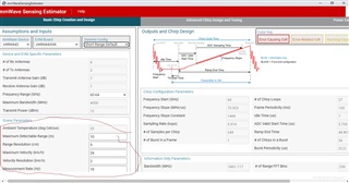
i have tried with "mmwave sensing estimator tool " for same design parameters of

Starting frequency (GHz) 60
Maximum range, Rmax (m) 2.72
Range resolution (cm) 5.3
Maximum velocity (m/s) 1.7
Velocity resolution (m/s) 0.0154

 it is observed thar calculated parameters(screenshots attached) are not matching with ""Design Guide: TIDEP-01023 Child-Presence and Occupant-Detection Reference Design Using 60-GHz Antenna on-Package mmWave Sensor",please refer page no:7(table 2.1) parameters".

question 3: kindly check and confirm incase Chirp design parameters are calculated using some other tools, kindly share the details of the same.

  • Hi Mani,

    It looks like you are using only the basic chirp creation and design. Can you please look into the Advanced Chirp design and tuning section.
    In this section you will essentially have control over the other parameters like idle time, num of chirps etc.

    Thanks,
    Kundan

  • hi kundan,

      thanks for your reply.i knew that there is an option like advance chirp design but which is useful post the estimation of all the chirp design parameters like frequency slope,sampling freq,ramp end time etc.

    please refer chirp design parameters to be used are mentioned under folder "C:\ti\radar_toolbox_1_30_01_03\tools\visualizers\InCabin_CPD_w_Classification_GUI\config_file\vod_6843_isk_frontMount_2row.cfg"

    profileCfg 0 60.00 2789 11 41 0 0 97.0 1 64 2200 0 0 36
    profileCfg 1 60.00 20 11 41 0 0 97.0 1 64 2200 0 0 36
    chirpCfg 0 0 0 0 0 0 0 1
    chirpCfg 1 1 1 0 0 0 0 2
    chirpCfg 2 2 1 0 0 0 0 4
    frameCfg 0 2 54 0 200 1 0

    its clear from .cfg file you have estimated two different chirp profile parameters for below Child presence detection system application requirement:

    Starting frequency (GHz) 60
    Maximum range, Rmax (m) 2.72
    Range resolution (cm) 5.3
    Maximum velocity (m/s) 1.7
    Velocity resolution (m/s) 0.0154

    (Note:as we aware AWR6843 isk has 3-TX antenna and 4-RX antenna with MIMO option.)

    1.how did you calculated these chirp design parameters?

    2.does it using mmwave sensing estimator tool ?

    3.if you have derived with some other tool or method, kindly share the details of the same.

    regards,

    Mani

    regards

  • Hi Mani,

    These are calculated as per the formulae incorporated within the sensing estimator itself.
    You can refer FMCW Radar Training Series (ti.com) to understand more about how slope, bandwidth, sampling rate affects the Max range, range resolution etc.

    I hope I have answered your question. Please let us know if you need any other additional details.

    Thanks,
    Kundan

  • dear kundan,

     thanks for your reply.i could understand TI reference documents and resources available on how these different parameters are calculated.

    i tried to derive these parameters using mmwave estimator tools for the same system Child presence detection system application requirement(as mentioned below):

    Starting frequency (GHz) 60
    Maximum range, Rmax (m) 2.72
    Range resolution (cm) 5.3
    Maximum velocity (m/s) 1.7
    Velocity resolution (m/s) 0.0154

    As i mentioned earlier(tool uses default ideal time ,adc_valid_start_time and caluctes other parameters like slope,ramp_end_time etc).screenshot of calculated parameters are attached for your reference.

    1.kindly check and let me how did you calculated below chrip parameters using mmwave estimator tools at your side?

    for profile 0:

    Idle time (μs) 2789
    ADC valid start time (μs) 11
    Ramp end time (μs) 41

    for profile 1:

    Idle time (μs) 20
    ADC valid start time (μs) 11
    Ramp end time (μs) 41

    common for both profiles:

    Sampling frequency (Msps) 2.2

    Number of samples per chirp 64

    Number of chirp loops 54

    "Ramp slope (MHz/μs) 97 

    2.how did you calculated same "Ramp slope (MHz/μs) 97" for both chirp profile using mmwave estimator tool?

    regards,

    mani

  • Hi, Mani:

    You can follow the following figure to use the mmwave sensing estimator

    Step 1) Goes to the middle tab (Advance Chirp Design and Tuning)

    step 2) Copy the CLI chirp configuration, and click on Auto-populate

    Note that there is some limitation, sensing estimator does not support multiple profileCfg.  So I modified the chirp slightly to use just one profileCfg.  

    step 3) Check the output

    Best,

    Zigang

  • You can always play with the each parameter and see in the output, how it changes the system parameters like range resolution, max range, and max velocity.   Depends on each application, the chirp tuning can be different.  But here is the thoughts I was using when design the chirps for this application.  

    1) I usually start with a lower ADC sampling rate, because longer chirping time results in a higher SNR, which is important in this application.  On the other hand, the max non-ambiguous Doppler value is not important in this application, instead Doppler resolution is more important to detect the very slow movement.  The idle time (2789us) between the loops is set long to get fine Doppler resolution. 

    2) I will increase the slope until the 4G bandwidth is just reached.  Because in this application, we prefer the best range resolution. 

    3) I will use the number of ADC sample to be just enough to reach my maximum range.  

    4) Set the number of loops as high as possible to fit into the radar cube memory.  

    5) The small idle time, ADC start time, and ramp end time needs to check the suggestions inside the mmWave studio tab rampTimingCalculator as below

    Best,

    Zigang