This thread has been locked.

If you have a related question, please click the "Ask a related question" button in the top right corner. The newly created question will be automatically linked to this question.

FDC1004: Calibration/Measurement of Capacitance

Part Number: FDC1004
Hi,
We are using the FDC1004DGSR part. 
Below is what we are reading - 
Capcitance value for every 15 seconds
# ./capsensor | grep GetCapacitance
GetCapacitance return value <nil> cap 1.2263946044810243
GetCapacitance return value <nil> cap 0.14561423563481177
GetCapacitance return value <nil> cap 0.02596784026825179
GetCapacitance return value <nil> cap 0.034503124523700655
GetCapacitance return value <nil> cap 0.01764212772443225
GetCapacitance return value <nil> cap 0.02773967383020881
GetCapacitance return value <nil> cap 0.020709495503734188
GetCapacitance return value <nil> cap 0.011869379667733578
GetCapacitance return value <nil> cap 0.0034865112025605854
GetCapacitance return value <nil> cap 0.017604023776863282
GetCapacitance return value <nil> cap 0.030006858710562415
GetCapacitance return value <nil> cap 0.004381953970431337
GetCapacitance return value <nil> cap 0.014022252705380277
GetCapacitance return value <nil> cap 0.013260173754000914
GetCapacitance return value <nil> cap 1.2303193110806279
-- Capacitance value is all around the place. 
-- We are expecting higher value. Just an FYI, above measurements are in Air.
Attaching our layout related to level sensor.
 Level Sensor PCB Layout
  • Darshan,

    Would you please provide some add'l information on your system, the sensor, and how you are using the device?

    Regards,
    John

  • Hi John,

    We are building liquid immersion system. Liquid is suppose to full submerge the system. If liquid level goes low, that is a concern as system will get hot.

    The measurements which we shared are the one in air mode. We want to trigger if Capacitance of the sensor goes low (by how much, not sure now).

    Immersion liquid have Dielectric constant from 2 to 10. So we are expecting Capacitance to go down by half to 10% when liquid level goes down.

    We have FR4 PCB with Er of the PCB material ~ 4, sensor is routed microstrip (Top PCB layer). Let's assume Effective Er ~ 2 (due to microstrip routing)

    Let's talk about sensor capacitance:

    Area of the capacitance plate ~ 1500 mils (trace length) x 2.5 mils (trace thickness) = 3750 sq. mils.

    Distance between 2 plates = 7mils

    So C = 2 x (8.85e-12) x 3750 / 7 ~ 8.85e-10 = 885pF (Rough estimate)

    Thanks,
    Darshan

  • Darshan,

    Thank you for the additional info.
    I will review it and have an update by COB on Tuesday.

    Regards,
    John

  • Darshan,

    Does your sensor utilize the FDC1004's active shield feature?
    The variability you are seeing may be due to external EMI.

    What do the connections between the sensor and the FDC1004 look like?
    Are they exclusively PCB traces, or is there a wire harness?
    Are they shielded? 

    Regards,
    John

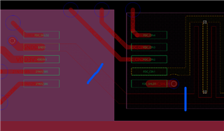
  • Hi John, We have SHLD1 pin connected to shape on 2nd Layer (just below the Sensor which is routed on Top Layer). We are only using CIN1 and GND as our capacitance sensor. We are not using CIN2, CIN3 and CIN4 pins. See photo below that shows SHLD1 routing that fully covers sensor traces. Let us know if the layout looks fine? Yellow shape is the CIN1 of the sensor, Green shape is the GND of the sensor and Blue shape is the SHLD1 of the sensor.

    What do the connections between the sensor and the FDC1004 look like? -- Layout snippet attached.

    Are they exclusively PCB traces, or is there a wire harness? -- They are exclusively PCB traces

    Are they shielded?  -- Yes, SHLD1 is used to shield the sensor connection on Layer2.

  • Darshan,

    What kind of behavior do you see if you disconnect the ground part of the sensor's connection?
    This would make the green part of your image floating.

    Regards,
    John

  • Hi John, Green signal is part of the PCB. There is no way we can make the GNDD floating. Do you see something wrong with the layout?

  • Darshan,

    Nothing is wrong with the layout.
    The source of the fluctuating readings isn't obvious, so I thought changing your sensor topology, and seeing if it has effect on the capacitance readings might provide some clues.

    Some more questions:

    1. Are you confident your power source for the device is stable and low noise?
    2. Are there any nearby noise sources?
    3. Can you share your schematic and layout files?

    Regards,
    John

  • Hi John,

    Sensor nets are spaced apart from nearby traces.

    We can measure 3.3V voltage ripple powering the sensor.

    Can you provide Shared Drive link for us to upload schematics and layout file?

    Another thing, Based on rough Capacitance calculation, what we measure is low. Does the Sensor needs to be calibrated or any registers you want to read?

    Thanks,
    Darshan

  • Darshan,

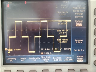
    The sensor waveform should look like a 25kHz stepped square wave:

    Does it look like this on your board?

    Your calculated estimate (885pF) is beyond the nominal range of the FDC1004 (-15pF - 15pF).

    I close this thread for now and reach out to you with an E2E friendship request.
    Please accept the request and we can exchange private messages - and files- via the messaging app.

    Regards,
    John

  • John, will get the measured waveform by today or tomorrow.

    We are not using your GUI, we are using our code.

    Please help review our code too.

  • Hello Darshan, 

    Just letting you know John is out of office for a few days but he did share your code with me. Let me know when you have the waveforms captured and I will take a look at your code in the meantime. 

    Best Regards, 

    Justin 

  • Will share waveforms by tomorrow. 

  • Hello Darshan, 

    I took a look at your code and didn't find anything that seemed like a problem. Along with the waveforms, can you post the unprocessed register read of the data out of the FDC1004? 

    Thank you, 
    Justin Beigel

  • Please find attached data you requested.

    msb(0) 22936 ---> Register 0, value 22936
    lsb(1) 15872 ---> Register 1, value 15872
    msb(2) 19860 ---> Register 2, value 19860
    lsb(3) 33280 ---> Register 3, value 33280

  • Hello Darshan, 

    It looks like the FDC1004 excitation isn't properly operating for your sensor. I am curious to see if disconnecting the GND portion of your sensor would improve the stability of this waveform. Based on the layout you provided, it seems like the GND trace is on an external layer of the PCB. Would it be possible to scrape away the copper at either of the following locations and recheck the sensor waveform? 

    Best Regards, 

    Justin Beigel

  • Please find scope shot after cutting GNDD trace.

    After GNDD trace cut

  • Hello Darshan, 

    Looks like cutting the GND trace didn't fix the waveform. There are a couple more things we can do to debug this issue: 

    • To isolate the sensor, would it be possible to remove the IC on the board and solder wires onto the pads to connect an EVM in? This way, the EVM FDC1004 can drive the sensor coils to see if the behavior is still the same. 
    • Is this happening on multiple boards or just 1? If just 1, have you tried replacing the IC on it yet? 

    Best Regards, 
    Justin Beigel

  • Hi Justin,

    Will measure signal swing on another board tomorrow. I will check with our lab team to see if we can remove the IC and power it externally and measure the signal.

    Thanks,

    Darshan

  • Hi Justin,

    We will order EVM and test one chip.

    We measured signal on another board and signal looks the same as other board. This issue is on all the board.

    Thanks,

    Darshan

    Signal measurement on 2nd board

  • Hello Darshan, 

    Thanks for confirming it is all boards. Based on the information, my hunch is that something about the sensor design is causing the problem. The last step to confirm it would be testing with the EVM to see if the EVM can drive your sensor on its own. Let us know once you get the EVM in and are able to perform the test. 

    Best Regards, 
    Justin Beigel