This thread has been locked.

If you have a related question, please click the "Ask a related question" button in the top right corner. The newly created question will be automatically linked to this question.

PGA970: PGA970

Part Number: PGA970

Hello,

When trying to calculate signal error and resolution for the PGA970 one eventually ends up at section 6.14 of the datasheet: Digital Demodulators 1 and 2. Here I notice the ENOB value of 15 bits.

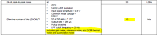
This is followed by the usual suspects that can be converted to LSB values (FSO, ppm/C, PSRR, etc). 

      1. My system needs to have a minimum resolution of 820 uV if I am running the LVDT at it's spec'd values. The demodulator max voltage is 2.5 V. So, using the ENOB I get the following, 2.5/2**(15+1) = ~ 38.1 uV resolution without adding in the other aforementioned non-idealities (FSO, ppm/C, PSRR). Does this calculation seem correct for the actual resolution this thing has?

      2. Are there other sources of signal error in this chip beyond what is stated in the electrical characteristics for the Digital Demodulators 1 and 2 - in terms of the ENOB value that is given and all that it encompasses?

I will have to add external amplification just like the EVAL board has in order to hit the 2.3Vrms 5kHz primary excitation voltage the LVDT was spec'd at in order to have a 0.044V/mm/Vex sensitivity and 20um resolution I desire, and that signal will need to still be attenuated down for the PGA970 to accept it I gathered. This will definitely introduce more error I will have to account for somehow. Any insight into this setup would be appreciated but I am mainly concerned with question 1.

  • Hi Nicholas,

        1. My system needs to have a minimum resolution of 820 uV if I am running the LVDT at it's spec'd values. The demodulator max voltage is 2.5 V. So, using the ENOB I get the following, 2.5/2**(15+1) = ~ 38.1 uV resolution without adding in the other aforementioned non-idealities (FSO, ppm/C, PSRR). Does this calculation seem correct for the actual resolution this thing has?

    See the section in the datasheet 7.3.1.21 on the Digital Demodulation.  The DC output in codes follows the formula 2 * A(mplitude) / 2.5π *2^23 to determine the LSB size (value of 1 count).  If we look at the maximum input amplitude of 2.5V, we end up with 2/π *2^23 = 5340354 codes (or counts).  This matches the data in Table 2 on page 26.  As the outcome is limited by noise we can simplify by using the 16-bit result.  Reviewing the table we see that for 2.5V and looking at the 16-bit result we get the value of one count as 2.5V/20860 or 119.8uV per count and 15 bit would double that to 239.6uV.

          2. Are there other sources of signal error in this chip beyond what is stated in the electrical characteristics for the Digital Demodulators 1 and 2 - in terms of the ENOB value that is given and all that it encompasses?

    There are many things that affect the overall outcome, including variations in the primary waveform and wiring to and from the transformer.  You would need to take into account an amplification errors (primarily offset, gain and associated drift).  As far as the ADC errors most of the error is dominated by what is shown in the table.  However, variations in the reference can show as either noise or gain error.  A simple RSS analysis will show which error sources dominate and which ones have little affect.

    Best regards,

    Bob B