This thread has been locked.

If you have a related question, please click the "Ask a related question" button in the top right corner. The newly created question will be automatically linked to this question.

IWRL6432: 2D Antenna Variant - The range is very low, cannot detect human.

Part Number: IWRL6432

Hi everyone,

For our project to detect humans, we used IWRL6432 radar sensor, and for the antenna design, we used 2D Antenna Variant, which promises us a very long distance to detect human (10 meters).

However, the range of the demo (motion and presence detection) is very low.

Its range is almost 2 – 2.5 meters when we use industrial visualizer to see, do you have any idea what would be the reason?

Do you have any suggestions to make it better? 

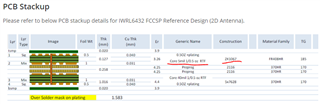
We only changed the “antGeometryCfg” parameter since we are using 2D Antenna Variant design from: https://dev.ti.com/tirex/content/radar_toolbox_2_00_00_06/docs/reference_designs/IWRL6432_FCCSP_Reference_Design/iwrl6432_FCCSP_reference_design.html


Can you guys help about this situation? Is there a way to fix this problem without changing the design? Or what might be the problem for such a short range?

We are considering to use antenna design from dev kit (IWRL6432BOOST) instead of 2D Antenna Variant, since dev kit is seems to be performing better according to our tests, but it is our plan B.

We would like you to confirm if the antenna design (from dev kit) is okay to use with 4 layer stackup?

Lastly, our custom board also will be inside an ABS box, will it effect the range? But I think electromagnetic waves should be able to pass the materials like ABS.

Thank you for your help,


Antenna design is same as the TI reference design (2D Antenna Variant).

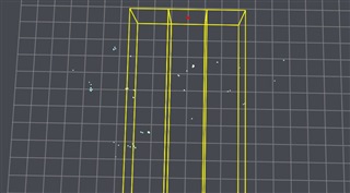
Our custom board's Antenna Design:

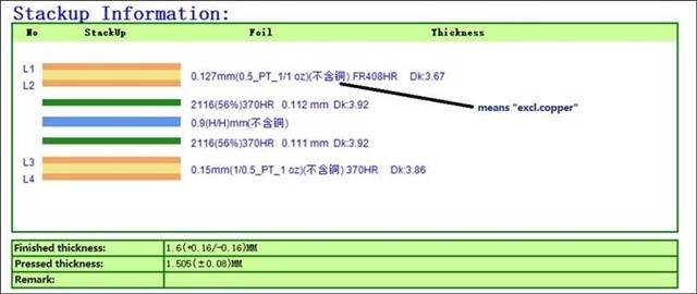
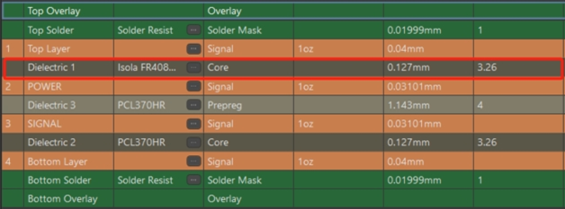
Current stackup of our board:

*Manufacturer suggested to use 0.15mm on the bottom layer to not delay the production (they had no 0.127mm thickness ready at that moment)

  • Hello.

    Could you provide the full demo configuration that you are using?  Also have you made any modifications to the demo source code?

    Sincerely,

    Santosh

  • We didn't make any modifications to the demo source code, and we've also tried the prebuilt code. This is the configuration we are using:

    % ***************************************************************
    % TrackingClassification_MidBw: Chirp configuration and
    % processing chain are designed to detect, localize, track, and
    % classify objects in indoor or outdoor environments.
    % This config utilizes ~1GHz BW (~20cm range resolution) and
    % enables all the available six antennas of the EVM.
    % The maximum unambigious range of this config is ~10m.
    % In this config, auto mode (major and minor) is enabled to track
    % objects with any kind of motion, including fine movements.
    % ***************************************************************
    sensorStop 0
    channelCfg 7 3 0
    chirpComnCfg 16 0 0 128 4 28 0
    chirpTimingCfg 6 32 0 40 60.5
    frameCfg 2 0 200 64 100 0
    antGeometryCfg 1 0 1 1 1 2 0 3 0 4 0 5 2.418 2.418
    guiMonitor 2 3 0 0 0 1 0 0 1 1 1
    sigProcChainCfg 32 2 3 2 8 8 1 0.3
    cfarCfg 2 8 4 3 0 12.0 0 0.5 0 1 1 1
    aoaFovCfg -70 70 -40 40
    rangeSelCfg 0.1 10.0
    clutterRemoval 1
    compRangeBiasAndRxChanPhase 0.0 1.00000 0.00000 -1.00000 0.00000 1.00000 0.00000 -1.00000 0.00000 1.00000 0.00000 -1.00000 0.00000
    adcDataSource 0 adc_data_0001_CtestAdc6Ant.bin
    adcLogging 0
    lowPowerCfg 1
    factoryCalibCfg 1 0 40 0 0x1ff000
    boundaryBox -3.5 3.5 0 9 -0.5 3
    sensorPosition 0 0 1.9 0 0
    staticBoundaryBox -3 3 0.5 7.5 0 3
    gatingParam 3 2 2 2 4
    stateParam 3 3 12 50 5 200
    allocationParam 6 10 0.1 4 0.5 20
    maxAcceleration 0.4 0.4 0.1
    trackingCfg 1 2 100 3 61.4 191.8 100
    presenceBoundaryBox -3 3 0.5 7.5 0 3
    microDopplerCfg 1 0 0.5 0 1 1 12.5 87.5 1
    classifierCfg 1 3 4
    baudRate 1250000
    sensorStart 0 0 0 0

    Best regards,

  • Burak,

    What is the thickness of your FR408HR? Are you using the dual-ply spread glass application?

    Do you follow the layout guidelines for the IWRL6432? Can you provide a better image of the PCB? Particularly of the GCPW traces? It looks like there may be some damage to the traces which would impact performance. 

    Thanks! 

    Blake

  • Blake,

    Our FR408HR's specs are shown as the table (Stackup Information) above. The manufacturer produced the board based on these specs:


    The issue might not be about the GCPW traces or damages, because we tested it with multiple boards (but the same FR408HR from same manufacturer), and we couldn't detect human after 2 meters on every board.

    Could the problem be about the quality of the FR408HR? Should we get and try FR408HR from another manufacturer? 

    Also, we actually don't know about "dual-ply spread glass application", should we specify this to the manufacturer before the order?

    Thanks and best regards,

  • Let me pull together some information for you. You'll receive a response before the end of the week. 

  • Hello Burak,

    I am sharing a tested configuration for higher range detection below. You can test with this.

    PresenceDetect_15m_HumanDetect.cfg

    I have some questions.

    1. Have you referred to the recommended stack up from IWRL6432 FCCSP Reference Design (ti.com) (also shown below)?

    For the antenna layer it is highly recommended to have a 2x1067 (dual ply) spread glass construction for the FR408HR material.

    2. What is the surface finish that has been used? In case of ENIG surface finish, the insertion loss will be more which will further cause poorer RF performance.

    3. From the image it is looking like the GND trace is entering the GCPW vacuum for one of the transmitters. Also, the RF traces for RXs are looking damaged. Could you make sure it is not the case?

    Below are answers to your questions:

    1. The IWRL6432BOOST EVM's antenna design would be OKAY to use with the 4-layer stack up if desired. In that case the antenna geometry modification won't be required.

    2. For other design factors for Radome, please refer to https://www.ti.com/lit/an/swra705/swra705.pdf. There are a number of design elements that need to be taken care like material dielectric constant, loss tangent, antenna to radome distance, rdaome wall thickness etc.

    Thanks and Regards

    Swarnendu

  • 1. Yes, we've referred to the recommended stackup.

    2. We contacted and double checked with the manufacturer that the surface finish is “Immersion Silver” as it is specified in reference design. We also asked about specifications (dual ply, spread glass) of the FR408HR material, waiting for their reply.

    3. This is another antenna photo from one of our PCB's:

    https://hizliresim.com/r6kqtuw

    As you can see, in this photo traces are more cleaner, but still we cannot detect human above 2 meters.


  • Hi Burak,

    Please let us know once you get reply from the manufacturer regarding the FR408HR material details.

    Have you checked with the configuration I previously sent you?

    Thanks 

    Swarnendu

  • Hi Swarnendu,

    Our manufacturer still didn't reply to our question, but we will let you know once we get the reply.

    For the configuration, we've tried it. The range is increasing a little bit, but there are so much noise when we look at the interface:

    There was only 1 person in this situation, but there are so many point clouds as you can see.

    Thanks and regards,

  • Thanks, Burak for the follow up.

    I am sharing another configuration for tracking. Please try with the same.

    Tracking_Improved.cfg

    However, in the layout side there are some major issues. We shall share the review feedback soon.

    Thanks and regards,

    Swarnendu