This thread has been locked.

If you have a related question, please click the "Ask a related question" button in the top right corner. The newly created question will be automatically linked to this question.

LDC1614: Strange oscillations measured over time

Part Number: LDC1614

Hi,

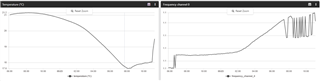
Has anyone seen the behaviour depicted in the attached images? The overall curve of the measurement is followed, but there clearly are oscillations coming from the readout.

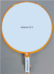
We have 2 custom antennas hooked up to the LDC1614 and they are at rest in a room where nobody goes. Fluctuations are mostly due to temperature and thermal dilation of the antenna assy.

Anyone has an idea of where this is coming from?

Best,

Xavier

  • Another image showing that sometimes there are no oscillations and sometimes there are. No changes in the config.

  • Hello Xavier, 

    I have a few questions for you regarding your implementation: 

    • What is the spacing between your two antennas? If they are very close to each other, is there a possibility to separate them and retest? 
    • Can you share your configuration for the LDC1614? 
      • Most importantly, I am curious about the DEGLITCH filter setting. Based on your screenshots, I would expect it to be set at the 10MHz cutoff. 
      • If possible, could you only enable channel 0 and set the DEGLITCH value to 3.3MHz to see if that decreases the noise for that channel?

    Best Regards, 

    Justin Beigel

  • Hi Justin,

    Here is the function that inits the LDC1614. We reset it to default at the beginning, so I believe the parameters that are not configured here are set to the default values.

    /*Set to maximum time for better resolution*/
    #define LDC1614_CONVERSION_TIME_INTERVAL 0xFFFF
    
    /*Set AUTOSCAN_EN to b1, RR_SEQUENCE to b00, DEGLITCH to b101 = 10 MHz*/
    #define LDC1614_MUX_CONFIGURATION 0x820D
    
    bool init_ldc1614(void){
    
      uint16_t mfg_id = 0xFFFF;
    
      // Initialize Interface with ldc1614 Driver
      interface_ldc1614(&ldc1614);
    
      // Init TWI
      if(app_i2c_init()){
    
        // Get Sensor Information to validate, then configure the sensor
        LDC1614_read_sensor_infomation(&mfg_id);
    
        if(mfg_id == LDC1614_MFG_ID){
          //NRF_LOG_INFO("LDC1614 MFG ID: 0x%04X", mfg_id);
          
          if(LDC1614_reset_sensor() != LDC1614_NO_ERROR)
          {
            NRF_LOG_INFO("ERROR WITH LDC1614 RESET");
            return false;
          }
    
          LDC1614_is_sleeping = false;
    
          // LDC1614 configurations is recommended to be done while the device sleeps
          if(!LDC1614_sleep())
          {
            NRF_LOG_INFO("ERROR WITH LDC1614 SLEEP");
            return false;
          }
    
          if(LDC1614_set_conversion_time(LDC1614_CHANNEL_0, LDC1614_CONVERSION_TIME_INTERVAL) != LDC1614_NO_ERROR)
          {
            NRF_LOG_INFO("ERROR WITH LDC1614 CONVERSION TIME 0");
            return false;
          }
    
          if(LDC1614_set_conversion_time(LDC1614_CHANNEL_1, LDC1614_CONVERSION_TIME_INTERVAL) != LDC1614_NO_ERROR)
          {
            NRF_LOG_INFO("ERROR WITH LDC1614 CONVERSION TIME 1");
            return false;
          }
    
          if(LDC1614_set_conversion_offset(LDC1614_CHANNEL_0, 0) != LDC1614_NO_ERROR)
          {
            NRF_LOG_INFO("ERROR WITH LDC1614 OFFSET 0");
            return false;
          }
    
          if(LDC1614_set_conversion_offset(LDC1614_CHANNEL_1, 0) != LDC1614_NO_ERROR)
          {
            NRF_LOG_INFO("ERROR WITH LDC1614 OFFSET 1");
            return false;
          }
    
          if(LDC1614_set_LC_stabilize_time(LDC1614_CHANNEL_0, 0x040) != LDC1614_NO_ERROR)
          {
            NRF_LOG_INFO("ERROR WITH LDC1614 STABILIZE TIME 0");
            return false;
          }
    
          if(LDC1614_set_LC_stabilize_time(LDC1614_CHANNEL_1, 0x200) != LDC1614_NO_ERROR)
          {
            NRF_LOG_INFO("ERROR WITH LDC1614 STABILIZE TIME 1");
            return false;
          }
    
          if(LDC1614_set_clock_dividers(LDC1614_CHANNEL_0, 1, 8) != LDC1614_NO_ERROR)
          {
            NRF_LOG_INFO("ERROR WITH LDC1614 CLOCK 0");
            return false;
          }
    
          if(LDC1614_set_clock_dividers(LDC1614_CHANNEL_1, 2, 1) != LDC1614_NO_ERROR)
          {
            NRF_LOG_INFO("ERROR WITH LDC1614 CLOCK 1");
            return false;
          }
    
          if(LDC1614_set_mux_config(LDC1614_MUX_CONFIGURATION) != LDC1614_NO_ERROR)
          {
            NRF_LOG_INFO("ERROR WITH LDC1614 MUX CONFIG");
            return false;
          }
    
          if(LDC1614_set_driver_current(LDC1614_CHANNEL_0,19) != LDC1614_NO_ERROR)
          {
            NRF_LOG_INFO("ERROR WITH LDC1614 CURRENT 0");
            return false;
          }
    
          if(LDC1614_set_driver_current(LDC1614_CHANNEL_1,22) != LDC1614_NO_ERROR)
          {
            NRF_LOG_INFO("ERROR WITH LDC1614 CURRENT 1");
            return false;
          }
    
          if(!LDC1614_wake_up())
          {
            NRF_LOG_INFO("ERROR WITH LDC1614 AWAKE");
            return false;
          }
          return true;
        }
        return false;
      }
      return false;
    }

    We have an inductive antenna with fixed capacitor (Ch0) and a capacitive antenna with fixed inductor (Ch1). They are on the same FPC, and the LDC1614 is located on that FPC. They are close, but I don't think they would interfere.

    You are right, we are set to 10 MHz.

    Best,

    Xavier

  • Note that there might be a connection between temperature and the oscillations. Since the only thing that changes the resonant frequency of the antennas seems to be the temperature, one might think it would have an effect on the measurement stability?

  • Hello Xavier, 

    Thank you for the additional information. I have a couple follow up questions for you:

    • Could you measure the sensor waveforms on an oscilloscope while they are having the noisy behavior? By taking a differential across the INxA and INxB pins, you should see a clean sinusoidal wave. Additionally, you can double check the amplitude of the wave is between 1.2V and 1.8V during the noisy behavior. 
    • Do you know what the Q factor of your LC tank on each sensor channel is? 
    • You mention the frequency shift due to temperature change causes a difference in the measurement noise. Does this also occur if you alter the frequency through a normal target interaction while maintaining a stable temperature? 

    Best Regards, 

    Justin Beigel

  • Hi Justin,

    We'll check that out. It might take some time, we got some people on vacation now.

    Best,

    Xavier

  • Hello Xavier, 

    No worries. Just let me know when you have an update or if any new questions arise in the meantime. 

    Best Regards, 

    Justin Beigel