This thread has been locked.

If you have a related question, please click the "Ask a related question" button in the top right corner. The newly created question will be automatically linked to this question.

AWRL6432BOOST: mcan - DRX (Message Stored to Dedicated Rx Buffer) interrupt cannot be triggered

Part Number: AWRL6432BOOST

mcan - DRX (Message Stored to Dedicated Rx Buffer) interrupt cannot be triggered

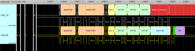
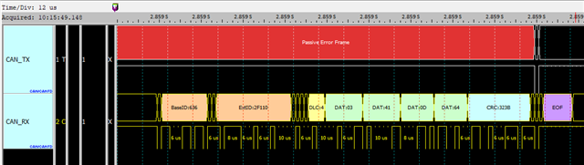
The measurement wave line received two pieces of data, but did not trigger the interrupt DRX (Message Stored to Dedicated Rx Buffer)

Print the value of intrStatus as follows

intrStatus = 0x80 

The relevant code is as follows:

/* Maximum TX Buffer + TX FIFO, combined can be configured is 32 */
#define APP_MCAN_TX_BUFF_CNT (1U)
#define APP_MCAN_TX_FIFO_CNT (0U)
/* Maximum TX Event FIFO can be configured is 32 */
#define APP_MCAN_TX_EVENT_FIFO_CNT (0U)
/* Maximum RX FIFO 0 can be configured is 64 */
#define APP_MCAN_FIFO_0_CNT (0U)
/* Maximum RX FIFO 1 can be configured is 64 and
* rest of the memory is allocated to RX buffer which is again of max size 64 */
#define APP_MCAN_FIFO_1_CNT (0U)

static void App_mcanIntrISR(void *arg)
{
uint32_t intrStatus;

intrStatus = MCAN_getIntrStatus(gMcanBaseAddr);
MCAN_clearIntrStatus(gMcanBaseAddr, intrStatus);

if (MCAN_INTR_SRC_TRANS_COMPLETE ==
(intrStatus & MCAN_INTR_SRC_TRANS_COMPLETE))
{
SemaphoreP_post(&gMcanTxDoneSem);
}

/* If FIFO0/FIFO1 is used, then MCAN_INTR_SRC_DEDICATED_RX_BUFF_MSG macro
* needs to be replaced by MCAN_INTR_SRC_RX_FIFO0_NEW_MSG/
* MCAN_INTR_SRC_RX_FIFO1_NEW_MSG respectively */
if (MCAN_INTR_SRC_DEDICATED_RX_BUFF_MSG ==
(intrStatus & MCAN_INTR_SRC_DEDICATED_RX_BUFF_MSG))
{
SemaphoreP_post(&gMcanRxDoneSem);
}

return;
}

  • Hi,

    The intrStatus of 0x80 means that a message was lost, which can be thrown if a FIFO overflows. There is likely some issue with filtering here. A couple of questions:

    Are you running one of our MCAN demos? And have you made any modifications to it?

    Does the ID match the ID used in the your project code?

    The MCAN users manual has a good diagram describing the filtering process: See page 77 https://www.bosch-semiconductors.com/media/ip_modules/pdf_2/m_can/mcan_users_manual_v331.pdf 

    Is accept non-matching frames set to 0? Even if we are using a buffer and not a FIFO, if there is a non-matching frame and accept-non-matching-frames is set to 0, it could still be sent to the FIFO and reported back as a overflow/lost frame.

    Please let us know,

    Regards,

    Tim

  • Dear Tim,

    I referred to the sample code (SDK_05_04_00_01-mcan_external_read_write) and modified the parts we needed. I also connected the ECU simulator, measured the TX&RX signals, and obtained normal reply data (as shown in the picture in the article), but could not trigger the receive interrupt. When I reboot and transfer a piece of data, I get two interrupts and get intrStatus = 0x8200 and intrStatus = 0x80 respectively.

    Below is the status of my scratchpad settings.Thanks!

    [Cortex_M4_0]
    [MCAN] External read - write test, application started ...
    [MCAN] === MCAN initialization parameters ===
    [MCAN] fdMode = 0
    [MCAN] brsEnable = 0
    [MCAN] txpEnable = 0
    [MCAN] efbi = 0
    [MCAN] pxhddisable = 0
    [MCAN] darEnable = 1
    [MCAN] wkupReqEnable = 1
    [MCAN] autoWkupEnable = 1
    [MCAN] emulationEnable = 1
    [MCAN] emulationFAck = 0
    [MCAN] clkStopFAck = 0
    [MCAN] wdcPreload = 0xff
    [MCAN] tdcConfig.tdcf = 0xa
    [MCAN] tdcConfig.tdco = 0x6
    [MCAN] tdcEnable = 1
    [MCAN] ======================================
    [MCAN] === MCAN configuration parameters ===
    [MCAN] monEnable = 0
    [MCAN] asmEnable = 0
    [MCAN] tsPrescalar = 0xf
    [MCAN] tsSelect = 0x0
    [MCAN] timeoutSelect = 0x0
    [MCAN] timeoutPreload = 0xffff
    [MCAN] timeoutCntEnable = 0
    [MCAN] =====================================
    [MCAN] === MCAN Global Filter Configuration parameters ===
    [MCAN] filterConfig.rrfe = 1
    [MCAN] filterConfig.rrfs = 1
    [MCAN] filterConfig.anfe = 1
    [MCAN] filterConfig.anfs = 1
    [MCAN] ===================================================
    [MCAN] === MCAN Message RAM Configuration Parameters ===
    [MCAN] lss = 1
    [MCAN] lse = 1
    [MCAN] txBufCnt = 1
    [MCAN] txFIFOCnt = 0
    [MCAN] txBufMode = 0
    [MCAN] txEventFIFOCnt = 0
    [MCAN] rxFIFO0Cnt = 0
    [MCAN] rxFIFO0OpMode = 0
    [MCAN] rxFIFO1Cnt = 0
    [MCAN] rxFIFO1OpMode = 0
    [MCAN] rxBufElemSize = 7
    [MCAN] rxFIFO0ElemSize = 7
    [MCAN] rxFIFO1ElemSize = 7
    [MCAN] txEventFIFOWaterMark = 0
    [MCAN] rxFIFO0WaterMark = 0
    [MCAN] rxFIFO1WaterMark = 0
    [MCAN] flssa = 0x0
    [MCAN] flesa = 0x4
    [MCAN] txStartAddr = 0xc
    [MCAN] txBufElemSize = 7
    [MCAN] txEventFIFOStartAddr = 0x0
    [MCAN] rxFIFO0StartAddr = 0x0
    [MCAN] rxFIFO1StartAddr = 0x0
    [MCAN] rxBufStartAddr = 0x54
    [MCAN] =================================================
    [MCAN] === MCAN Standard Message ID Filter Element ===
    [MCAN] sfid2 = 0x98daf110
    [MCAN] sfid1 = 0x98db33f1
    [MCAN] sfec = 0x7
    [MCAN] sft = 0x1
    [MCAN] ===============================================
    [MCAN] === MCAN Extended Message ID Filter Element ===
    [MCAN] efid1 = 0x98db33f1
    [MCAN] efec = 0x7
    [MCAN] efid2 = 0x98daf110
    [MCAN] eft = 0x1
    [MCAN] ===============================================
    After transmitting the messages, it will wait to recieve ten messages for test to pass ...
    [MCAN] SendMCAN_cmd ...
    [MCAN] === MCAN Tx Buffer element ===
    [MCAN] id = 0x98db33f1
    [MCAN] rtr = 0
    [MCAN] xtd = 1
    [MCAN] esi = 0
    [MCAN] dlc = 3
    [MCAN] brs = 1
    [MCAN] fdf = 0
    [MCAN] efc = 1
    [MCAN] mm = 0xaa
    [MCAN] data[0] = 0x2
    [MCAN] data[1] = 0x1
    [MCAN] data[2] = 0xd
    [MCAN] ==============================
    [MCAN] SendMCAN_cmd finish! protStatus.lastErrCode = 0, protStatus.dlec = 7, protStatus.pxe = 0
    [MCAN] Wait for Rx completion ...

  • Hi,

    Have you double checked that the message ID matches the demo?

    Can you also describe in more detail what changes you've made to the demo on your end?

    Monday is a U.S. holiday, so responses may be delayed.

    Regards,

    Tim

  • Dear Tim,

    The transmission settings are dlc = 3、xtd = 1 and fdf = 0, the message ID of the transmitted data is 0x98db33f1, the message ID of the received data is 0x98db33f1 and 0x98daf110, The main purpose is to handle receiving data of 0x98daf110, and also adjust the rate to 500Kbps. Made these changes. Can you help confirm whether any register settings are incorrect?

    Thanks!

  • Thanks for the update.

    I will post a replay here next week.

    Regards,

    Tim

  • Transmission part:
    [MCAN] txBufCnt = 1
    [MCAN] txFIFOCnt = 0
    [MCAN] txBufMode = 0
    [MCAN] txEventFIFOCnt = 0
    As set up above, why intrStatus = 0x8200 instead of 0x0200?

    Received part:
    [MCAN] filterConfig.rrfe = 0
    [MCAN] filterConfig.rrfs = 0
    [MCAN] filterConfig.anfe = 0
    [MCAN] filterConfig.anfs = 0
    [MCAN]lss=0
    [MCAN]lse=1
    [MCAN] rxFIFO0Cnt = 0
    [MCAN] rxFIFO0OpMode = 0
    [MCAN] rxFIFO1Cnt = 0
    [MCAN] rxFIFO1OpMode = 0
    [MCAN] rxBufElemSize = 7
    [MCAN] rxFIFO0ElemSize = 7
    [MCAN] rxFIFO1ElemSize = 7
    [MCAN] efid1 = 0x636
    [MCAN] efec = 0x7
    [MCAN] efid2 = 0x2f110
    [MCAN] eft = 0x1
    I don’t know where the setting is incorrect, the value obtained is intrStatus = 0x8

  • Hi,

    Please allow me until tomorrow to provide a response.

    Regards,

    Tim

  • Hi,

    A couple of things to discuss:

    • Both ends of the CAN line should be terminated with a 120 ohm resistor between the CAN low and CAN high lines to prevent reflections from impedance mismatching - is this the case?
    • I'm assuming all the nodes have the same timing parameters, but putting this here to confirm those settings are correct.

    In canfd_lld.c, can you set a breakpoint to see if we are receiving buffer interrupts or FIFO interrupts (lines 222/260 respectively). It would be helpful to know which of these if statements we are going into.

    in the mcan_external_read_write.c, after the RX completion SemaphoreP_pend, can you call MCAN_getRxFIFOStatus so we can check that the get/put indices are changing as we are getting data? The function may need to be modified to get from the correct FIFO0 or FIFO1.

    I'd like to just confirm you just changed the message ID and the rate to 500kbps? No other changes?

    Regards,

    Tim

  • Hi Tim,

    I have confirmed that the 120 ohm resistor is correct. I cannot set breakpoints in canfd_lld.c to debug because it should be a lib. In addition, the MCAN_INTR_SRC_DEDICATED_RX_BUFF_MSG condition cannot be established, so SemaphoreP_pend will not pass.

    Yes, the rate has been modified to 500Kbps. There is no problem with this part. The TX ID is 0x98db33f1 and the RX ID will be 0x98daf110. Currently, only the register value in the article is set and the program structure is not modified. I think it is part of the register. The setting is incorrect! Thank you!

  • Hi,

    A couple questions on you msg IDs. Are you making the proper configuration changes to use extended ID mode? Standard message IDs are 11 bits while extended message IDs are 29 bits. Your IDs that you are using are >29 bits, so perhaps the filtering is seeing that and discarding the message because its ID is too long. The same thing could happen if you are using an extended ID but are only configured to use standard message mode. I suggest changing the message IDs to something very short / simple (less than 11 bits). That way we can make sure that the IDs are not causing this issue.

    If that doesn't work. I'd request from you some code snippets of the code you are running. It would be good to get a sense of three things:

    - In App_mcanInitMsgRamConfigParams() can you list out the assigned values of all the parameters listed in that function?

    - Did you modify any of the code after the SemaphoreP_pend mentioned in our previous replies?

    - In App_mcanIntrISR(), can you add another if statement at the end in accordance with the comment using MCAN_INTR_SRC_RX_FIFO0_NEW_MSG and not MCAN_INTR_SRC_DEDICATED_RX_BUFF_MSG. This will post that semaphore if we get the message in the FIFO and not the buffer. You may need to use FIFO1 here as necessary.

    Regards,

    Tim

  • The previously uploaded image was compressed by the system, so we use a link instead:
    drive.google.com/.../1nbQq_MVXcIlSW1ja3pvC_7EhTwhPIIzN


    Yes, I have set the extended ID mode. In fact, looking at the measured waveform picture, the Base ID is 0x636 and the Ext ID is 0x2F110. We cannot change the ID because it is a standard established by the automotive OBDII.

    I have not modified any code after SemaphoreP_pend.

  • Hi,

    A couple more points and questions. If you are using buffer only mode, you can only use 1 ID at a time. You have EFID1 and EFID2 set up here, so you'll need to make some changes. If you want to receive 0x2F110, then you need to swap that ID over to EFID1. EFID2 needs to explicitly be set to 0x0 as well.

    Please base your register values on the following from one of your previous posts:

    [Cortex_M4_0]
    [MCAN] External read - write test, application started ...
    [MCAN] === MCAN initialization parameters ===
    [MCAN] fdMode = 0
    [MCAN] brsEnable = 0
    [MCAN] txpEnable = 0
    [MCAN] efbi = 0
    [MCAN] pxhddisable = 0
    [MCAN] darEnable = 1
    [MCAN] wkupReqEnable = 1
    [MCAN] autoWkupEnable = 1
    [MCAN] emulationEnable = 1
    [MCAN] emulationFAck = 0
    [MCAN] clkStopFAck = 0
    [MCAN] wdcPreload = 0xff
    [MCAN] tdcConfig.tdcf = 0xa
    [MCAN] tdcConfig.tdco = 0x6
    [MCAN] tdcEnable = 1
    [MCAN] ======================================
    [MCAN] === MCAN configuration parameters ===
    [MCAN] monEnable = 0
    [MCAN] asmEnable = 0
    [MCAN] tsPrescalar = 0xf
    [MCAN] tsSelect = 0x0
    [MCAN] timeoutSelect = 0x0
    [MCAN] timeoutPreload = 0xffff
    [MCAN] timeoutCntEnable = 0
    [MCAN] =====================================
    [MCAN] === MCAN Global Filter Configuration parameters ===
    [MCAN] filterConfig.rrfe = 1
    [MCAN] filterConfig.rrfs = 1
    [MCAN] filterConfig.anfe = 1
    [MCAN] filterConfig.anfs = 1
    [MCAN] ===================================================
    [MCAN] === MCAN Message RAM Configuration Parameters ===
    [MCAN] lss = 1
    [MCAN] lse = 1
    [MCAN] txBufCnt = 1
    [MCAN] txFIFOCnt = 0
    [MCAN] txBufMode = 0
    [MCAN] txEventFIFOCnt = 0
    [MCAN] rxFIFO0Cnt = 0
    [MCAN] rxFIFO0OpMode = 0
    [MCAN] rxFIFO1Cnt = 0
    [MCAN] rxFIFO1OpMode = 0
    [MCAN] rxBufElemSize = 7
    [MCAN] rxFIFO0ElemSize = 7
    [MCAN] rxFIFO1ElemSize = 7
    [MCAN] txEventFIFOWaterMark = 0
    [MCAN] rxFIFO0WaterMark = 0
    [MCAN] rxFIFO1WaterMark = 0
    [MCAN] flssa = 0x0
    [MCAN] flesa = 0x4
    [MCAN] txStartAddr = 0xc
    [MCAN] txBufElemSize = 7
    [MCAN] txEventFIFOStartAddr = 0x0
    [MCAN] rxFIFO0StartAddr = 0x0
    [MCAN] rxFIFO1StartAddr = 0x0
    [MCAN] rxBufStartAddr = 0x54
    [MCAN] =================================================
    [MCAN] === MCAN Standard Message ID Filter Element ===
    [MCAN] sfid2 = 0x98daf110
    [MCAN] sfid1 = 0x98db33f1
    [MCAN] sfec = 0x7
    [MCAN] sft = 0x1
    [MCAN] ===============================================
    [MCAN] === MCAN Extended Message ID Filter Element ===
    [MCAN] efid1 = 0x98db33f1
    [MCAN] efec = 0x7
    [MCAN] efid2 = 0x98daf110
    [MCAN] eft = 0x1
    [MCAN] ===============================================
    After transmitting the messages, it will wait to recieve ten messages for test to pass ...
    [MCAN] SendMCAN_cmd ...
    [MCAN] === MCAN Tx Buffer element ===
    [MCAN] id = 0x98db33f1
    [MCAN] rtr = 0
    [MCAN] xtd = 1
    [MCAN] esi = 0
    [MCAN] dlc = 3
    [MCAN] brs = 1
    [MCAN] fdf = 0
    [MCAN] efc = 1
    [MCAN] mm = 0xaa
    [MCAN] data[0] = 0x2
    [MCAN] data[1] = 0x1
    [MCAN] data[2] = 0xd
    [MCAN] ==============================
    [MCAN] SendMCAN_cmd finish! protStatus.lastErrCode = 0, protStatus.dlec = 7, protStatus.pxe = 0
    [MCAN] Wait for Rx completion ...

    Please also ensure EFEC is 0x7 still as well.

    One last question. If we concatenate the Base ID 0x636 and the Ext ID 0x2F110 we get 0x18DA F110. Why then, is the ID we are using 0x98DAF110? Can we change it to start with a 1 as a sanity check?

    Regards,

    Tim