This thread has been locked.

If you have a related question, please click the "Ask a related question" button in the top right corner. The newly created question will be automatically linked to this question.

FDC2212: Resonance Frequency

Part Number: FDC2212

Tool/software:

Dear TI Team,

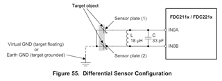
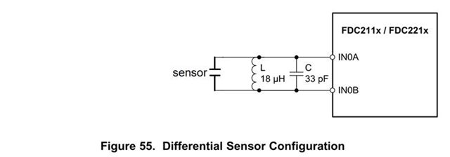
we wanted to set up the FDC in its differential operating mode.
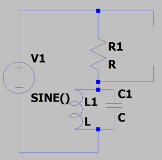
Therefore we chose a SMD ceramic capacitator with 20 pF (+5 pF for our sensor electrodes) and a shielded SMD inductance of 20 uH to set up our LC-circuit.
Thus, the calculated resonance frequency is 7.1 MHz. On a function generator we measured the resonance frequency of our LC-Circuit, (tolerances aside) confirming this resonance frequency.

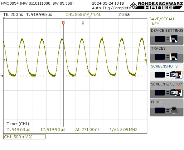
After connecting the LC-circuit to the FDC (with traces, as short as possible and not surrounded by copper while the LC-circuit is not surrounded by copper as well) we encountered a problem: The resonance frequency shifted significantly, now reaching only about 3.7 MHz. Signals are shown in the attached image, but also over I2C we measure this frequency.

Is there any explanation why we measure this frequency?

Kind regards

  • Hi,

    Welcome to E2E and thanks for posting your question to the sensors forum. 

    I’ll take a look at your question and provide feedback by end of day Tuesday, May 28 as Monday is a holiday here in the US  

    Best regards,

    Jesse

  • Hi,

    There are a few things that could be contributing to this.

    • Do you know the capacitance of your scope probes? The capacitance of the scope can impact the frequency of oscillation. Do you read out different values over I2C when the scope probes are not connected?
    • The FDC2212 Cin pins also have a parasitic capacitance of 4pF (as shown in the electrical characteristics table that should be considered for the measurement)
      • Section 10.2.3.2 of the datasheet shows an example of where an 18uH inductor and 33pF capacitor are used, but additional pin, trace, and wire capacitance accounts for 20pF, so the total capacitance is 53pF.
    • What are your clock configuration settings in the FDC2212 (i.e. CHx_FIN_SEL)? This settings can impact the measurements if not accounted for in your calculations.
    • This is less likely because you didn't see it in the function generator measurement, but self-resonant frequency could be a factor with the inductor. See section 10.2.3.3 of the FDC2x1x datasheet for more information on self-resonant frequency.

    Can you provide more information on the following?

    • How are you confirming the resonant frequency with your function generator setup?
    • You mentioned using the differential sensor configuration. Does your schematic match what is shown in Figure 55 of the FDC2x1x datasheet?
    • Make sure there's no target object nearby when taking the measurements. Is the sensor in the same location when measuring with the function generator setup and when you are measuring with the FDC2212?

    Best regards,

    Jesse

  • Hello Jesse,

    Thank you for your response!

    We tried to clarify each point in the following:

    There are a few things that could be contributing to this.

    • Do you know the capacitance of your scope probes? The capacitance of the scope can impact the frequency of oscillation. Do you read out different values over I2C when the scope probes are not connected?

    We disconnected the sensor electrodes to further isolate the problem. Measuring the frequency with our oscilloscope probes now results in a frequency of 3.8MHz. The probes have a (rated) capacitance of 13pF. When disconnecting the probes, and analysing the frequency over I2C, we get 4.6MHz. When using I2C with the probes connected, we read 3.7MHz.

    • The FDC2212 Cin pins also have a parasitic capacitance of 4pF (as shown in the electrical characteristics table that should be considered for the measurement)

    Thank you for the reminder! It seems like we did not take that into account. The FDC should then resonate at 7.26MHz (without sensors, 20pF + 4pF, 20uH), which it sadly does not.

    • Section 10.2.3.2 of the datasheet shows an example of where an 18uH inductor and 33pF capacitor are used, but additional pin, trace, and wire capacitance accounts for 20pF, so the total capacitance is 53pF.

    Sadly, we have no adequate tools to measure this. But since we now disconnected the sensor electrodes (and cables) we would need to have a trace capacitance of 35pF to justify the frequency we are measuring, which we think is unlikely.

    • What are your clock configuration settings in the FDC2212 (i.e. CHx_FIN_SEL)? This settings can impact the measurements if not accounted for in your calculations.

    We left the settings in their default state except:

    CH0_FIN_SEL = b10

    CH1_FREF_DIVIDER = b00’0000’0001

    • This is less likely because you didn't see it in the function generator measurement, but self-resonant frequency could be a factor with the inductor. See section 10.2.3.3 of the FDC2x1x datasheet for more information on self-resonant frequency.

    The self-resonant frequency of the Inductor is well above 20MHz, so its easily outside of the critical range.

    Can you provide more information on the following?

    • How are you confirming the resonant frequency with your function generator setup?

    We connected the LC-circuit as shown below:

    We then measured the voltage drop over R while doing a frequency sweep. Upon reaching the resonance frequency of the LC-circuit the voltage drop reached its minimum, thus confirming the resonance frequency.

    • You mentioned using the differential sensor configuration. Does your schematic match what is shown in Figure 55 of the FDC2x1x datasheet?

    Not exactly, we use the sensor to detect, if the 2 electrodes of the sensor get closer together, so the circuit looks like this:

    • Make sure there's no target object nearby when taking the measurements. Is the sensor in the same location when measuring with the function generator setup and when you are measuring with the FDC2212?

    Yes, the location did not change.

     We appreciate you taking the time to help us out! If there are any further details you would like to know, feel free to message us again.

    Thank you in advance and best regards!

  • Hi,

    We left the settings in their default state except:

    CH0_FIN_SEL = b10

    CH1_FREF_DIVIDER = b00’0000’0001

    Are you using CH0 and CH1?

    Not exactly, we use the sensor to detect, if the 2 electrodes of the sensor get closer together, so the circuit looks like this:

    To detect if the two sensor electrodes are getting closer together, you may be better off grounding one of the electrodes and using the single-ended configuration, as shown below

    Do you have an FDC2214EVM you could use to test your sensor electrodes and configuration?

    Best regards,

    Jesse

  • Hello Jesse,

    that was a typing error, we only use one channel. 

    Unfortunately we do not have the evaluation board available, but we will try using the single-ended configuration. 

    Best regards!

  • Thanks for the clarification.

    Please let me know if you have additional questions after trying the single-ended configuration.

    Best regards,

    Jesse