This thread has been locked.

If you have a related question, please click the "Ask a related question" button in the top right corner. The newly created question will be automatically linked to this question.

DCA1000EVM: ADC Raw Data Capture Mismatch of Data length (with IWR6843ISK-ODS)

Part Number: DCA1000EVM
Other Parts Discussed in Thread: IWR6843ISK-ODS, MMWAVEICBOOST

Tool/software:

Dear TI Support Team

I am trying to interpret the raw ADC data received from the DCA1000EVM board over ethernet. The problem is that the number of samples I receive does not match the number of samples I expect (there samples missing in the order of a few dozen). I am using the following hardware:

  • IWR6843ISK-ODS (PROC075 Rev. A)
  • MMWAVEICBOOST (PROC074B-001)
  • DCA1000EVM (PROC048 Rev. A)

The 3 devices are stacked together and powered via the 5V socket of the BOOST board. The BOOST board and the DCA1000 are connected via the 60-pin connector. The BOOST board is connected to my PC via USB (to configure the sensor) and the DCA1000 is connected to my PC via ethernet in order to stream the ADC data. Both the communication with the sensor (i.e. sending the config and starting it) as well as the communication with the DCA1000 are done using a Python script.

The sensor is running the Out-Of-Box-Demo and configured using the commands stored in the following file: 7041.config.cfg

A JSON file containing a datacard_config (similar to the one described in mmwave_sdk_user_guide.pdf) is given here: 

{
    "dataLoggingMode": "raw",
    "dataTransferMode": "LVDSCapture",
    "dataCaptureMode": "ethernetStream",
    "lvdsMode": 2,
    "dataFormatMode": 3,
    "packetDelay_us": 5,
    "ethernetConfig": {
        "DCA1000IPAddress": "192.168.33.180",
        "DCA1000ConfigPort": 4096,
        "DCA1000DataPort": 4098
    },
    "ethernetConfigUpdate": {
        "systemIPAddress": "192.168.33.30",
        "DCA1000IPAddress": "192.168.33.180",
        "DCA1000MACAddress": "12-34-56-78-90-12",
        "DCA1000ConfigPort": 4096,
        "DCA1000DataPort": 4098
    }
}

According to this configuration, I would expect the following number of ADC samples when recording 10 frames:

numFrames * numLoops * chirpsPerLoop * numRx * numADCsamples = 10 * 9 * 3 * 4 * 249 = 268920  (for both I and Q, with every value occupying 2 Bytes, totalling to 4 * 268920 = 1075680 Bytes of data)

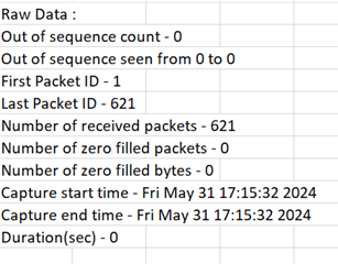
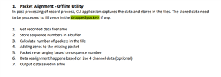
The procedure generally works, however, when parsing the received data I get too few ADC samples. The data exchange over Ethernet looks as follows whene analyzed in wireshark:

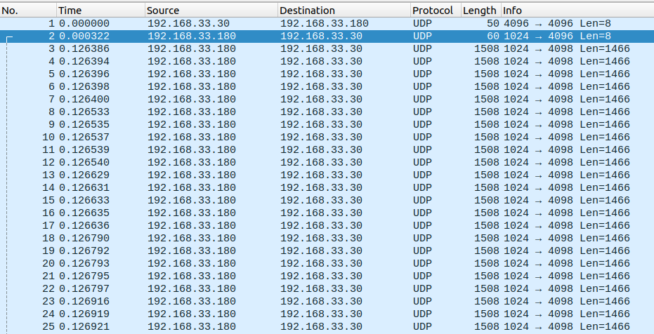
As far as I understand, the first two and the last packet are config exchanges ('5' at the start for 'Start record' and System status 0x1 for 'No LVDS data' at the end). In-between we have 738 packets of data length 1466 and a final packet of data length 938. According to the DCA1000SVM Data Capture Card User's Guide (Rev. A), each packet starts with a sequence number of 4 bytes and a byte count of 6 bytes, meaning that the length of the ADC data itself is 10 bytes less than indicated above. This results in a total number of bytes of 738 * 1456 + 928 = 1075456, which is 224 bytes less than expected.

The number of received ADC values is also different depending on the number of requested frames, but never correct and I cannot really find a pattern that would explain the situation.

Due to this, I am really unsure whether to trust the data I receive. Can you help me out here?

Thank you for a response and best regards,

Selvin

  • HI, Selvin:

    How did you control the system to capture 10 frames of data?

    Best,

    Zigang

  • Hi Zigang

    Good point, that is actually something I forgot to mention. I control this via the control command frameCfg I send to the sensor. So the parameter 'number of frames' is set to 10 (instead of the 0 in the .cfg file I attached in my original post - this is because I handle the number of frames to record separately in my Python script).

    The procedure that is executed in my Python script roughly looks like this:

    • Set up communication to radar and DCA
    • Configure DCA
    • Send config to radar (including the number of frames to transmit, in this case 10)
    • Tell the DCA to start recording
    • Tell the sensor to start sensing (sensorStart command)
    • Wait for the DCA to transmit all the data, indicated by the system status code for 'No LVDS data'

    I hope this helps to clarify the situation.

    Best regards,

    Selvin

  • Hi, Selvin:

    Your order looks correct to me.  But since it is your python script that we can not help much.  Can you try our capture tool and see whether it has similar problems?

    The capture tool is located inside radar toolbox. 

    https://dev.ti.com/tirex/explore/node?node=A__ABI-ZASWhWKVBrIeYEG4hA__radar_toolbox__1AslXXD__LATEST

    Best,

    Zigang

  • Hi Zigang

    I have now analyzed the problem by recording with both the capture tool inside the radar toolbox mentioned by you as well as the mmWaveStudio. To compare the transmitted data I have mainly relied on Wireshark, as at least the size and structure of the transmitted UDP packages seems to be consistent between these methods.

    Using mmWaveStudio: When requesting data using the same .cfg file as mentioned before (i.e. 10 frames), the received number of bytes is actually 621*1456=904'176 instead of the expected 1'075'680, so significantly lower than when using my Python script.

    With the capture tool by TI, one can set the number of frames to display at the end as well as the time to record. When setting the number of frames to record via the .cfg file to 10, the number of received bytes is equivalent to the mmWaveStudio case. When requesting the tool to display 10 frames, the matlab script throws an error (which makes sense, as there is not enough data for 10 bytes). The tool works best if the number of frames in the .cfg file is set to 0 (=infinite number of frames). In that case, the requested number of frames can be plotted without difficulty (given the recording time is long enough).

    Analyzing the matlab script at ti/radar_toolbox_2_10_00_04/tools/Adc_Data_Capture_Tool_DCA1000_CLI/gui/rawDataCaptureGUI_DCA1000CLI.m, I conclude that the DCA sends the full data as expected (i.e. the set number of ADC samples for every tx, rx, loop, frame, etc.) but potentially does not transmit some of the values at the end. Is that assumption correct? Is there a specific reason why this is done?

    Here are some of the files from my tests (logs exported by the tool as well as a wireshark recording (pcap)):

    mmWaveStudio recording:  recording_mmWaveStudio.zip

    ADC Data Capture Tool Recording (from radar toolbox): recording_capture_tool.zip

    Recording with my python script: recording_python.zip

    Thank you for your help!

    Best regards,

    Selvin

  • HI, Selvin:

    From the recording_005_Raw_LogFile.xml recorded with capture tool,  the number of zero filled bytes is all zero.

    So, there is no missing data during the capture.  Therefore I agree with you, it must be the last sets of data is not transmitted.  Do you have to be that precise?  Could you program to capture 12 frames, and then process only the first 10 frames. 

    Best,

    Zigang

  • Hi Zigang

    Thanks for the quick response.

    It is generally no problem if I have to request more frames than I actually need. I just want to be sure that the data that I do receive belongs to the frames I am interested in (i.e. there is no data missing somewhere in the middle).

    Can you thus confirm that I can trust the data I receive as long as I make sure that all packets are received (by checking their ID)?

    Best regards,

    Selvin

  • Hi, Selvin:

    You are right.  I would recommend you to read the documentation under the following folder. 

    C:\ti\mmwave_studio_02_01_01_00\mmWaveStudio\ReferenceCode\DCA1000\Docs

    Best,

    Zigang