This thread has been locked.

If you have a related question, please click the "Ask a related question" button in the top right corner. The newly created question will be automatically linked to this question.

AMC6821-Q1: I2C Communication Failed

Part Number: AMC6821-Q1

Tool/software:

Hi Team,

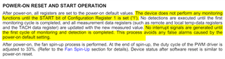
Based on below post that I2C communication is blocked within spin-up time(2 sec).

=> AMC6821-Q1: Cannot control when chip initialize early

=> We encounter the same issue and after 2 sec, the I2C write and read are all expected as what we set.

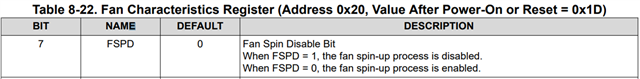
I notice the FSPD is "0" so once the VDD is powered, it will directly enter into spin-up cycle and no way to change that, is that correct?

After VDD is given, If we keep FSPD as "0", once the fan stops or an RPM is detected below the minimum speed, it will enter spin-up time again and lost the I2C communication for 2 sec again?

=> Assume we use the same STIMEx setting.

And why we have this 2s spin-up time design? What's the purpose of it?

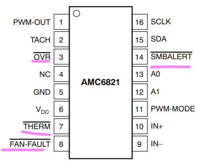
Customer use below 4 OD pin as indicator for SoC to judge whether we should start the I2C communication with AMC6821-Q1.

They said they notice these 4 pins might toggle so might not be a good indicator for SoC.

My question is whether the toggling phenomenon might happen randomly within above 2s spin-up time?

If this toggling phenomenon is due to certain fault, could we still check the 0x02(Device Status Registers) to know what happened within 2s spin-up time?

=> Maybe the WRITE function is blocked but READ function is available?

Looking forward to your reply.

Thank you.

  • There is a misunderstanding in the linked post. As you stated, the default STIME is 2 seconds. The linked post states that I2C communication is unavailable during STIME of 0.2s (200ms) but the default at power-on is actually 2s. Therefore, communication is available during STIME. This is because it was confirmed to work after 200ms in the linked post. I suspect there are other factors contributing to the delay that are system dependent and also configuration dependent (ie the desired configuration, and how it is used after configured.)

    1. Yes, FSPD is 0 at power-on default and there is no way to change the default.
    2. As stated above, spin-up is not preventing I2C communication.
    3. The text explains that spin-up overcomes the initial fan inertia by providing 100% at fan power-on.
    4. The text explicitly states that no false alarms will occur during power-on. If toggling is being observed by the MCU, it must be noise. What is the pull-up resistor used for these OD pins? 
    5. As stated above, I2C is available at power-on and is not blocked by spin-up.

    thanks,

    ren

  • Hi Ren,

    We use 10k ohm PU on those pins.

    So once the device power on(VDD) and spin-up ongoing, the I2C R/W function are all available within 2s?

    I notice the monitoring function are available until we write the START bit to "1".

    Before then, no detection/monitoring will be done so what we saw on those pins(14/3/7/8) during power on is impossible?

  • Yes, that is what the text says. Have you looked at the pins with oscilloscope during power-on?

    thanks,

    ren