This thread has been locked.

If you have a related question, please click the "Ask a related question" button in the top right corner. The newly created question will be automatically linked to this question.

IWRL6432AOP: Data transfer in I2C slave mode

Part Number: IWRL6432AOP

Tool/software:

Hi,

My customer would like to make IWRL6432AOP as I2C slave, the master would initiate data transfer. when one frame process complete, radar would info master through GPIO, then master would initial I2C data read from radar slave. I found below link on I2C config as slave, it mentions the slave target address, my question is how to decide the memory address for I2C? Can u share one example include code work on radar as slave, and code work on master to read the radar slave?

https://e2e.ti.com/support/sensors-group/sensors/f/sensors-forum/1299117/iwrl6432boost-i2c-slave-setting/4954430#4954430
A
ndy
  • Hey Andy,

    As discussed in the linked E2E post, the included code configures the radar to as a target/slave device. You can set the radar I2C target address by toggling the "Show Advanced Config" option on and setting the "Own Target Address" field to any value between 0x00 and 0x7F. 

    All radar target devices start off in receiver mode in which the device will wait for data from a controller. Once a command has been received by the controller, the device can switch to transmitter mode. This mode is entered only if the target address byte is the same as its own address and the R/W bit has been transmitted.

    Regards,

    Kristien

  • Hi, Kristien

    I did a simple test, the code ande the results are as follows.

    uint8_t txBuffer[1];
    uint8_t rxBuffer[2];
    int32_t status;
    uint8_t deviceAddress;
    I2C_Handle i2cHandle;
    I2C_Transaction i2cTransaction;

    I2C_Transaction_init(&i2cTransaction);
    i2cTransaction.writeBuf = txBuffer;
    i2cTransaction.writeCount = 1;
    i2cTransaction.readBuf = rxBuffer;
    i2cTransaction.readCount = 2;
    txBuffer[0] = 0xaa; 
    // i2cTransaction.targetAddress = deviceAddress;
    i2cTransaction.controllerMode = 0;

    if(status == SystemP_SUCCESS)
    {
         DebugP_log("[I2C] sensor trans succ!! . \r\n");

    }
    else
    {
         DebugP_log("[I2C] sensor trans failed. \r\n");
    }

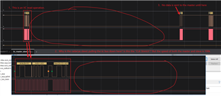
    Below is the data captured with the logic analyzer. I want the radar(iic slave) to return 0xaa,but it was 0x00.

    My question is which register to set when the master initiates the communication so that the slave correctly returns the value of txBuffer?

    Can u share one example include code work on radar as slave, and code work on master to read the radar slave?
  • Hello,

    After configuring the radar I2C mode to target/slave mode, you need to call the I2C_transfer function which will allow the controller to acknowledge and send back information. In compliance with "The I2C Bus Specification" v2.1 document mentioned in the xWRLx432 TRM, the I2C controller itself is addressable but no register addressing is used. Upon receiving a start byte, target address, and read bit, the radar I2C controller will send back an acknowledgement and n bytes of data determined by the writeCount.

    Regards,

    Kristien

  • Hi,Kristien

    With the radar as slave, I can now wirte data correctly.Thanks.

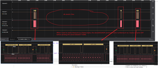
    But when I read the data,something occur as follows.Why?

  • Hello,

    Give me an extra day to look into this.

    Regards,

    Kristien

  • Hi, Kristien

    Is there any result on the above question?

    I used three methods(anther IWRL6432AOP、other MCU、a usb to iic converter) to be the master, and they all showed the same bus pull down phenomenon.

    In addition, the slave(IWRL6432AOP) can only send data after it has been pulled down the bus for a certain period of time if IWRL6432AOP is also acting as the master. However, when mcu and converter act as master, after the bus is pulled down, SDA and SCL are always low.

  • Hello,

    It is likely that the observed behavior of the I2C signals is clock stretching. How long is the period that the clock is pulled low? Is the stretch time consistent or does it vary greatly? Keep in mind that an ACK will involve pulling the SDA low, so its possible that the SDA and SCL are both held low due to clock stretching.

    Regards,

    Kristien

  • As I said before, the slave(6432) will only send data if 6432 is also acting as master. In a complete read operation, the bus pull down time is as follows:9ms and 42 ms. Each period is fixed.

    However, when mcu and converter act as master, after the bus is pulled down, SDA and SCL are always low.

    Have you tried using 6432AOP as an iic slave? Can the data transfer normally? After your test is completed, can you give an example of a slave? Hopefully there will be a clear result.

  • Hey,

    Yes, we have tested reading from 6432AOP as an I2C target/slave with the code linked in the previous thread. Additionally, I wanted to confirm: are you receiving the correct data from the 6432AOP when attempting to read from the device with a host device? 

    Note that clock stretching is inherent to I2C to help transfers stay in sync. You can try adjusting the clock speed or change transfer modes between blocking or interrupt. 

    Furthermore, the initial 9 ms delay could be a result of the I2C switching from target/slave-receiver to target/slave-transmitter.

    Regards,

    Kristien

  •  If 6432AOP is also acting as master, I can recivece the correct data  from the slave(also 6432AOP).But something occur as follows:

    however when mcu and converter act as master, after the bus is pulled down, SDA and SCL are always low.

    Furthermore, could you please send me the master and slave codes of your tests. Especially the master code.Thanks

  • Hello.

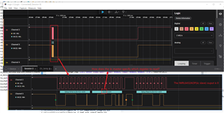
    We were not able to recreate the clock stretching issue.  I have attached my timing diagram below.  I am using the aardvark tool to send I2C messages to the device configured in target mode.  To be able to use target mode you must set the controllerMode field of the i2cTransaction struct to 0 and also set up the txbuffer in the i2c_read example in the SDK.  Is the example you are basing your code off of?

    Sincerely,

    Santosh

  • Yes, my code is currently modified based on the iic_read project.The ”clk stretch“ phenomenon occurs all the time as follow:

    Also, I'd like to see the complete  timing diagram of a read operation.

    And here is the  complete code (iic_read.c):

    /*
     *  Copyright (C) 2018-2021 Texas Instruments Incorporated
     *
     *  Redistribution and use in source and binary forms, with or without
     *  modification, are permitted provided that the following conditions
     *  are met:
     *
     *    Redistributions of source code must retain the above copyright
     *    notice, this list of conditions and the following disclaimer.
     *
     *    Redistributions in binary form must reproduce the above copyright
     *    notice, this list of conditions and the following disclaimer in the
     *    documentation and/or other materials provided with the
     *    distribution.
     *
     *    Neither the name of Texas Instruments Incorporated nor the names of
     *    its contributors may be used to endorse or promote products derived
     *    from this software without specific prior written permission.
     *
     *  THIS SOFTWARE IS PROVIDED BY THE COPYRIGHT HOLDERS AND CONTRIBUTORS
     *  "AS IS" AND ANY EXPRESS OR IMPLIED WARRANTIES, INCLUDING, BUT NOT
     *  LIMITED TO, THE IMPLIED WARRANTIES OF MERCHANTABILITY AND FITNESS FOR
     *  A PARTICULAR PURPOSE ARE DISCLAIMED. IN NO EVENT SHALL THE COPYRIGHT
     *  OWNER OR CONTRIBUTORS BE LIABLE FOR ANY DIRECT, INDIRECT, INCIDENTAL,
     *  SPECIAL, EXEMPLARY, OR CONSEQUENTIAL DAMAGES (INCLUDING, BUT NOT
     *  LIMITED TO, PROCUREMENT OF SUBSTITUTE GOODS OR SERVICES; LOSS OF USE,
     *  DATA, OR PROFITS; OR BUSINESS INTERRUPTION) HOWEVER CAUSED AND ON ANY
     *  THEORY OF LIABILITY, WHETHER IN CONTRACT, STRICT LIABILITY, OR TORT
     *  (INCLUDING NEGLIGENCE OR OTHERWISE) ARISING IN ANY WAY OUT OF THE USE
     *  OF THIS SOFTWARE, EVEN IF ADVISED OF THE POSSIBILITY OF SUCH DAMAGE.
     */
    
    #include <stdio.h>
    #include <string.h>
    #include <inttypes.h>
    #include <kernel/dpl/DebugP.h>
    #include "ti_drivers_open_close.h"
    #include "ti_board_open_close.h"
    #include <drivers/i2c.h>
    
    //*****************************************************************************
    // Defines
    //*****************************************************************************
    
    #define I2C_READ_TARGET_ADDR            (0x50U)
    #define I2C_READ_LEN                    (2U)
    
    //*****************************************************************************
    // Typedefs
    //*****************************************************************************
    
    
    //*****************************************************************************
    // Function prototypes
    //*****************************************************************************
    
    static void i2c_read_error_handler(uint16_t sample, int32_t status);
    
    //*****************************************************************************
    // Local Functions
    //*****************************************************************************
    
    uint32_t cnt = 0;
    uint8_t         txBuffer[2];
    void i2c_read_main(void *arg0)
    {
        uint16_t        sample;
        int32_t         status;
        uint8_t         rxBuffer[I2C_READ_LEN];
        I2C_Handle      i2cHandle;
        I2C_Transaction i2cTransaction;
    
        Drivers_open();
        Board_driversOpen();
    
        i2cHandle = gI2cHandle[CONFIG_I2C0];
    
        DebugP_log("[I2C] Read data ... !!!\r\n");
    
        /* Set default transaction parameters */
        I2C_Transaction_init(&i2cTransaction);
    
        /* Override with required transaction parameters */
        i2cTransaction.readBuf      = rxBuffer;
        i2cTransaction.readCount    = I2C_READ_LEN;
    //    i2cTransaction.targetAddress = I2C_READ_TARGET_ADDR ;
        i2cTransaction.writeBuf   = txBuffer;
        i2cTransaction.writeCount = 2;
        txBuffer[0] = 0x77;
        txBuffer[1] = 0x88;
        i2cTransaction.controllerMode = 0;
    
        /* Read 20 samples and log them */
        for(sample = 0; sample < 10; sample++)
        {
            DebugP_log("[I2C] sensor trans start.... %d. \r\n", cnt++);
            status = I2C_transfer(i2cHandle, &i2cTransaction);
            if(status == I2C_STS_SUCCESS)
            {
                DebugP_log("[I2C] Sample %u: %u\r\n", sample, rxBuffer[0]);
            }
            else
            {
                i2c_read_error_handler(sample, status);
            }
        }
    
        DebugP_log("[I2C] Read data ... DONE !!!");
        if(status == SystemP_SUCCESS)
        {
            DebugP_log("All tests have passed!!\r\n");
        }
        else
        {
            printf("Some tests have failed!!\r\n");
        }
    
        Board_driversClose();
        Drivers_close();
    
        return;
    }
    
    static void i2c_read_error_handler(uint16_t sample, int32_t status)
    {
        switch(status)
        {
            case I2C_STS_ERR:
                DebugP_log("[I2C] Sample %u: Generic error occurred", sample);
                break;
            case I2C_STS_ERR_TIMEOUT:
                DebugP_log("[I2C] Sample %u: Timeout error occurred", sample);
                break;
            case I2C_STS_ERR_NO_ACK:
                DebugP_log("[I2C] Sample %u: No acknowledgement received", sample);
                break;
            case I2C_STS_ERR_ARBITRATION_LOST:
                DebugP_log("[I2C] Sample %u: Arbitration lost", sample);
                break;
            case I2C_STS_ERR_ACCESS_ERROR:
                DebugP_log("[I2C] Sample %u: Bus Access error occurred", sample);
                break;
        }
    
        return;
    }
    

  • Hello.

    Yes, my code is currently modified based on the iic_read project.The ”clk stretch“ phenomenon occurs all the time as follow:

    Could you provide the timescale/axis for the reading on your logic analyzer?  From what it looks like the clock stretching isn't apparent, so I wanted to see the time axis as well for comparison

    Also, I'd like to see the complete  timing diagram of a read operation.

    This is the complete timing diagram.  The device software that we used for testing simply sends a controller(master) read and we captured the behavior as the read happens.  Prior to this, both the SCL and SDA lines are pulled high.  The only difference between your example and mine is the length of the buffer and write count, both are 1.

    Sincerely,

    Santosh