Tool/software:
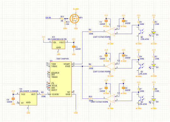
I have a custom encoder project where I want to measure the time between three gates monitored by IR TX and RX points, Couple of questions around the circuit above
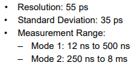
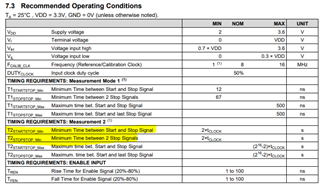
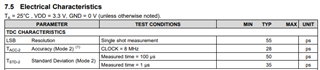
1) My average pulse durations between start signal and last stop signal will be 200uS and as fast as 1uS the comparators is in the nS range, is my understanding correct here that will be fine for the desired resolution ?
2) I saw an application note that you can monitor and detect more then 1 stop signal so will the above implementation work to provide me two duration between start and two stops ?
3) Looking at the resolution and delays. is a <1uS average error doable ?