This thread has been locked.

If you have a related question, please click the "Ask a related question" button in the top right corner. The newly created question will be automatically linked to this question.

AWR2944EVM: Sample applications not working.

Part Number: AWR2944EVM
Other Parts Discussed in Thread: AWR2944

Tool/software:

Hi TI team,

We’re trying to evaluate AWR2944 EVK. This is connected to the obstacle detection during door opening scenario we explored last year.

Basically, we’re not able to run the precompiled firmware; the only one we can run fails when we try to send a configuration and start. My colleague has describe the issue in detail below. We think the issue could be mismatch between the hardware and SDK versions. Could you point us to a direction.

Here’s the version info

  • HW: AWR2944 EVK rev D
  • SDK: mmwave_mcuplus_sdk_04_04_01_02
  • Radar_toolbox_2_10_00_04

 More details:

The labs we’ve tried to demo:

  1. 2944 OOB Object Data over CAN
  2. High End Corner Radar
  3. Nonos oob 2944
  4. Out of Box Demo

We seem to be experiencing similar issues with them all, seeming to stem from configuration file

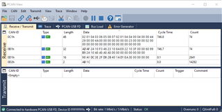
First, 2944 OOB Object Data over CAN

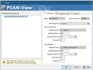
When running this one we go through the normal process outlined in the readme. Put the device in UART boot mode, flash the sbl and appimage, then switch the device to QSPI boot mode and power cycle. While trying to use the “automotive visualizer” we don’t really see any error codes being printed out in the console, but after going through the steps (select demo, select interface, connect, select configuration, start and send configuration), nothing happens. We’ve tried going through the UART interface and CAN interface, both with the same result. For reference, we are using the XDS USB port and I’ve tried both CAN ports on the EVK, but are still not able to see any data being visualized.

High End Corner Radar

We go through the same process as above (change boot mode, flash, change boot mode, power cycle, run visualizer). We will also select the HECR demo on the GUI. This is the only one that we’ve actually got it to visualize any data. However, we can only get it to work if we do not send a configuration (Start without send configuration button). If we try to select one of configurations included in the demo, this error will be continuously logged:

ERROR: No data detected on COM Port, read timed out

        Be sure that the device is in the proper mode, and that the cfg you are sending is valid

Nonos oob 2944

This one we tried both the Automotive visualizer and the web based mmWave Demo Visualizer.

In the automotive visualizer, we experience the same error code as the high end corner radar.

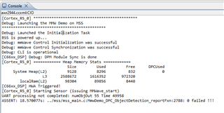
But I see that in the users guide it is recommended to use the web based mmWave Demo Visualizer on Chrome. To begin, we are able to connect to the device, however when trying to create a configuration on the GUI and send, the only thing that is printed is “Skipped” and when we try to load one from the PC, all the configs are loaded, but when it sends the final sensorStart, we get this error printed.

Debug: Init Calibration Status = 0xffe

After searching around on the forums, I found a post that says this error correlates to an error in the chirp config, but this happens when we try all of the provided config files. Also for reference we are using the TDM processing chain, with the TDM config files.

Finally, Out of Box Demo

This one we just tried using the mmWave Demo Visualizer, and when we first connect, the ability to configure the radar from the GUI disappears and gives a message that says to load a configuration from the PC. Since there doesn’t seem to be any included configuration file on this example, I tried the same ones from the Nonos oob 2944 example, because it seemed to be the most similar.

After skipping all of the unsupported commands, we see this same error.

Debug: Init Calibration Status = 0xffe

Is there any support you guys can provide us, we are trying to evaluate the radar.

Sincerely,

Richard

  • Hi Richard,

    Can you try running the demo present in the SDK? 

    Test using the prebuilt binary - "C:\ti\mmwave_mcuplus_sdk_04_04_01_02\mmwave_mcuplus_sdk_04_04_01_02\ti\demo\awr294x\mmw\awr2944_mmw_demoDDM.appimage"

    Regards,

    Samhitha

  • Hi Samhitha,

    This one is working with the included chirp configurations. Does this give any insight on what could be wrong with the other ones?

    Sincerely,

    Richard

  • Hi Richard,

    • 2944 OOB Object Data over CAN: If you are using PCAN-USB, can you try using PCAN-View and see if you are getting data over CAN. For this demo, we are using CAN-A instance.
    • For High End Corner Radar (HECR) demo, you don't need to send the configuration. The CLI is bypassed. Check high_end_corner_radar\src\2944\demo\mss\mmw_cli_HECR.c file to find the configuration that is being used.
    • Nonos oob 2944: Only DDM is supported. 
    • Out of Box Demo: This has the projectspec that is used to import the demo present in the SDK to CCS. So, you can use the configuration from mmwave_mcuplus_sdk_<ver>\ti\demo\awr294x\mmw\profiles\ddm_awr2944. And this CCS project is for DDM demo.

    Regards,

    Samhitha

  • Hi Samhitha,

    Isn't the automotive visualizer supposed to display the data output from the CAN lines? (at least that is how it seems from the user's guide)

    There are also no CAN parameters listed in the user's guide, but from looking through the code, I came up with these:

    However, after sending the configuration with the automotive visualizer, then connecting on PCAN-View, there is no activity on the lines. (using CAN instance A)

    Is there a possibility we have any discrepancy with the version of the board/version of SDK?

    For High End Corner Radar (HECR) demo, so there is no way to send a configuration when using the pre-compiled binary?

    For Nonos oob 2944, even trying the DDM version with DDM configuration files, we still see the same errors. Also, if TDM version is not supported why is there a pre-compiled binary included in the toolbox?

    Sincerely,

    Richard

  • Hi Richard,

    Isn't the automotive visualizer supposed to display the data output from the CAN lines?

    Yes, you should be able to see the plots in the visualizer. As you have already said that you don't see any output, I asked you to check it in PCAN-View.
    Instead of using the visualizer, send the configuration through some terminal emulator like Tera Term and check the output using PCAN-View.

    The bit rate, clock frequency that you are using is correct.

    For High End Corner Radar (HECR) demo, so there is no way to send a configuration when using the pre-compiled binary?

    Yes, you cannot send configuration if you are using the prebuilt binary. If you want to use a different configuration, you update high_end_corner_radar\src\2944\demo\mss\mmw_cli_HECR.c  file with required configuration and rebuild the application.

    For Nonos oob 2944, even trying the DDM version with DDM configuration files, we still see the same errors.

    Open the serial ports in terminal emulator and send the configuration through Application/User UART and check the output by connecting to Data Port.

    Also, if TDM version is not supported why is there a pre-compiled binary included in the toolbox?

    This will be fixed or removed in the next release.

    Regards,

    Samhitha

  • Hi Samhitha,

    Sorry for the delayed response.

    First:

    Instead of using the visualizer, send the configuration through some terminal emulator like Tera Term and check the output using PCAN-View.

    I tried this with the 2944 OOB Object Data over CAN, and received this:

    And then no other data was streamed. The config file I used was "profile_3d_3Azim_1ElevTx_DDMA_awr2944_highRange.cfg" from the radar_toolbox_2_10_00_04 2944 OOB Object Data over CAN example.

    Where can I find what this data means?

    Next:

    Open the serial ports in terminal emulator and send the configuration through Application/User UART and check the output by connecting to Data Port.

    So I sent the configuration through XDS110 Class Application/User UART port at 115200 baud rate, and then connect the terminal to XDS110 Class Auxilary Data Port at 3125000 baud rate. I didn't get any configuration error with the same profile_3d_3Azim_1ElevTx_DDMA_awr2944_highRange configuration file from the above example, however there is no output on the data terminal.

    Sincerely,

    Richard

  • Hi Richard,

    And then no other data was streamed.

    In profile_3d_3Azim_1ElevTx_DDMA_awr2944_highRange.cfg, all the parameters are 0. So, you didn't receive anything other than header.

    Check radar_toolbox_<ver>\source\ti\examples\2944_OOB_object_data_over_CAN\src\2944\include\mmw_output.h to understand the format of header.

    To understand different parameters of the commands in the configuration, refer to "C:\ti\mmwave_mcuplus_sdk_<ver>\mmwave_mcuplus_sdk_<ver>\docs\mmwave_mcuplus_sdk_user_guide.pdf".

    How many frames did you configure? You have received the header only for 1 frame.

    So I sent the configuration through XDS110 Class Application/User UART port at 115200 baud rate, and then connect the terminal to XDS110 Class Auxilary Data Port at 3125000 baud rate. I didn't get any configuration error with the same profile_3d_3Azim_1ElevTx_DDMA_awr2944_highRange configuration file from the above example, however there is no output on the data terminal.

    For which example did you test this? In 2944 OOB Object Data over CAN demo, the object data is not sent over UART. In my previous reply, I was referring to Nonos OOB demo (DDM).

    Regards,

    Samhitha

  • Hi Samhitha,

    How many frames did you configure? You have received the header only for 1 frame.

    I am using this configuration:

    sensorStop
    flushCfg
    dfeDataOutputMode 1
    channelCfg 15 15 0
    adcCfg 2 0
    adcbufCfg -1 1 0 0 1
    lowPower 0 0
    profileCfg 0 77 7 7 20.81 0 0 8.883 0 384 30000 0 0 36
    chirpCfg 0 5 0 0 0 0 0 15
    frameCfg 0 5 128 0 384 50 1 0
    guiMonitor -1 0 0 0 0 0 0
    cfarCfg -1 1 3 16 0 0 1 24.0 0 7 0 1
    cfarCfg -1 0 3 16 0 0 1 15.0 0 7 0 0
    compressionCfg -1 1 0 0.5 8
    intfMitigCfg -1 15 18
    localMaxCfg -1 6 40
    antennaCalibParams 0 1 0 1 0 1 0 1 0 1 0 1 0 1 0 1 0 1 0 1 0 1 0 1 0 1 0 1 0 1 0 1
    measureRangeBiasAndRxChanPhase 0 1.5 0.2
    analogMonitor 0 0
    calibData 0 0 0
    aoaFovCfg -1 -90 90 -90 90
    sensorStart

    The bolded 0, under the frameCfg should correspond with the number of frames.

    To understand different parameters of the commands in the configuration, refer to "C:\ti\mmwave_mcuplus_sdk_<ver>\mmwave_mcuplus_sdk_<ver>\docs\mmwave_mcuplus_sdk_user_guide.pdf".

    According to this document, sending a 0 in this place, should configure infinite number of frames (continuously scan and output detections) to my understanding.

    However, just in case, I changed it to 100 to see if it would stream out 100 frames, and it did not. This is the image of what streamed out. I think something else is going on here.

    Anyways, I loaded the project into CCS and ran it in a debug session, with the same setup (same configuration over UART, and CAN connection), and when I sent the configuration, I get this:

    And this on the CAN stream.

    It seems there is some other problem going on.

    For which example did you test this? In 2944 OOB Object Data over CAN demo, the object data is not sent over UART. In my previous reply, I was referring to Nonos OOB demo (DDM).

    Yes, I was also talking about the Nonos OOB demo (DDM). On here, the detections should stream out over UART, right? That is how it is supposed to work with the demo visualizer, right?

    Sincerely,

    Richard

  • Hi Richard,

    According to this document, sending a 0 in this place, should configure infinite number of frames (continuously scan and output detections) to my understanding.

    Yes, your understanding is correct.

    Anyways, I loaded the project into CCS and ran it in a debug session, with the same setup (same configuration over UART, and CAN connection), and when I sent the configuration, I get this:

    This issue occurs when the transfer is not completed. There is a macro - CAN_STREAM which is defined in this demo. If this is not defined the object data will be streamed over UART. So, the log UART(/CAN) processing not completed means the previous frame's transfer is not completed. 

    I don't see such issue when I run this demo. Check if the CAN-USB connection is disconnected between the transfer. Do not provide any breakpoint while running the demo as the transfer will not be completed.

    On here, the detections should stream out over UART, right? That is how it is supposed to work with the demo visualizer, right?

    Yes, for Nonos OOB demo, the object data is streamed over UART. Baudrate for Data port should be 852272. Follow the steps mentioned in NonOs OOB 2944 (ti.com) to run the demo using CCS. Halt the core to check if there is any assert.

    Regards,
    Samhitha
  • Hi Samhitha,

    From the OOB binary in the SDK, (which we were able to get working) is there a way to import that code into CCS using the resource explorer? The closest one I could find was from the radar toolbox (version mentioned above) but I'm not sure if that is the same, and I do experience some build issues on it. If that is the one, I can try to work out the build issues however.

    Please let me know,

    Sincerely,

    Richard

  • Hi Richard,

    CCS Projectspec for SDK demo is located at radar_toolbox_<dir>\source\ti\examples\Out_Of_Box_Demo\src\awr294x. Refer to Out Of Box Demo User Guide (ti.com) if you have any issues in importing the project.

    Regards,

    Samhitha