This thread has been locked.

If you have a related question, please click the "Ask a related question" button in the top right corner. The newly created question will be automatically linked to this question.

DRV5012: Non-uniform sampling frequency

Part Number: DRV5012

Tool/software:

Dear TI,

We're using the DRV5012 on a quadrature encoder for a 12V micro DC motor with a magnet disc that offers 3 pulses per revolution (PPR), i.e. 6 poles. The no load speed is specified at 20000 RPM but measuring with a tachometer yields approximately 19400RPM, FWIW. Given 20000 RPM, this results in 333,33 revolutions per second. At 3 PPR this yields 333,33 x 3 = 1000 PPS or Hertz, multiplying this times 2 (Nyquist) yields 2 kHz hence the 2.5 kHz of the DRV5012 should be sufficient to be able to measure the 1 kHz signal.

Now, my first question is: can I configure the DRV5012 in some way, with higher voltage possibly, to end up in the region 2.5 - 4.7 kHz and how can I test this? Currently the encoder is already powered with a 5V power supply.

In reality we are observing some issues with this encoder however (see screen capture below):

  1. Channel A seems to have missed a pulse though the small pulse width before is 430 us wide, which proves that the DRV5012 can measure at 2.325 kHz. In order to have aliasing the motor would have to spin at 23250 RPM, which according to the tachometer, the motor doesn't.
  2. The phase of the A & B signal also almost seems to be in sync while the hall sensors are correctly placed at 90 degrees, which at 3 PPR is correct (half a pole distance of 30 deg + a whole multiple of the pole distance of 90 deg).

This is a picture of the board:

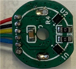
My second question is: would you recognize anything that we're missing here? Is there something wrong with the layout of the board?

Any support would be much appreciated.

Thanks in advance,

Jelle

  • Hello Jelle,

    Thanks for considering to use Texas Instruments.

    Within a selected range, I dont think you can adjust the sampling frequency.  However, I will check with my team.

    So my understanding is that you would like for your signals to be 90° out of phase.  To achieve that one, you should position the devices such that one device is in the middle of a pole and the other is on the split line between poles such as in the figure below.

    While the device does have a minimum sampling frequency of 1665Hz and likely has some jitter, im not sure that is the issue here as both A and B signals (I assume different devices) show extended pulses near each other.  Its possibly related to the location of the device and magnet and possibly some mechanical vibration.   If your magnet or board has any wobble, tilt, or runout on the shaft you might see some peculiar behavior.  I suspect it might be a little more pronounced the further you are from the device, as the fields get exponentially weaker with distance. 

    Not sure if you are aware of our simulation tool TIMSS (https://webench.ti.com/timss/design).  It might be useful in verifying that you have you have placed your devices such that the phase is 90° apart and will help you see how much margin for mechanical tolerance you have.  If you run a simulation in that tool, then you can export a json file that you can upload here so we can analyze your sensor magnet design, which will likely be helpful for followup inquiries.  One thing to note, if you use the tool, you will need to use figure 12 to account for the inner hall element location (tool center device with respect to the bottom center).

    In addition to supplying your relative magnet and device coordinates and dimensions (which a json from TIMSS can do), if you provide the part of your schematic involving the DRV5012 that will be helpful.