This thread has been locked.

If you have a related question, please click the "Ask a related question" button in the top right corner. The newly created question will be automatically linked to this question.

TMP110: ok

Part Number: TMP110

Tool/software:

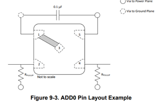
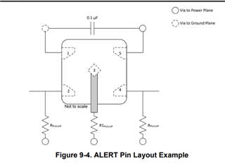
I am seeking clarification on the layout considerations for the temperature sensor part number. Is it mandatory to follow the layout example provided in the datasheet?

One of the layouts we have designed omits the 0.1 microfarad capacitor and pull-up resistors. Could you please explain the significance of these components in the board design as mentioned in the datasheet? Can I proceed without these components?

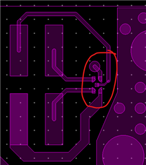
Please guide me on ensuring the correct layout for this temperature sensor. I would appreciate your insights into the design I have currently implemented without any capacitors or resistors.

Thank you.

  • Hi Rashmi,

    The pullup resistors are necessary for I2C communication since the SDA and SCL pins of TMP110 are open-draing. You may be able to get away with not using a pullup R on the SCL line only if the MCU has a push-pull interface. However, the SDA line does require a pullup for the device to control the line when needed. Without this, you will not be able to communicate with the device.

    The 0.1uF acts as a decoupling capacitor on the device and it is highly recommended to place it near the sensor to filter out as much noise that may be on the supply line as possible. Without the decoupling cap, any power supply noise performance specs cannot be guaranteed.

    Best regards,

    Simon Rojas