This thread has been locked.

If you have a related question, please click the "Ask a related question" button in the top right corner. The newly created question will be automatically linked to this question.

AWR2944: Unable to flash using UNIFLASH

Part Number: AWR2944
Other Parts Discussed in Thread: UNIFLASH,

Tool/software:

Hi everyone, 

We are trying to flash the AWR2944 on a custom PCB over UART via the UniFlash utility but have yet to have any success doing so. We have successfully flashed the AWR2944EVM using UniFlash (SBL Image: sbl_qspi.release.tiimage, App Image: awr2944_mmw_demoDDM.appimage) but when attempting to flash the same files to the AWR2944 on our custom PCB, the progress bar gets to about 1/3 of completion and then fails to complete the flash. We get the following errors across the console: 

[INFO] Cortex_R5_0: Initialization complete.
[INFO] Cortex_R5_0: Sending UART Uniflash image at location C:\ti\uniflash_8.7.0\deskdb\content\TICloudAgent\win\ccs_base\mmWave\gen2/images/sbl_uart_uniflash.release.tiimage
[ERROR] Cortex_R5_0: XMODEM send failed, no response OR incorrect response from EVM OR cancelled by user, power cycle EVM and run this script again !!!
[INFO] Cortex_R5_0: UART Uniflash image sent.
[INFO] Cortex_R5_0: Sending SBL image at location C:/Users/REDACTED/Documents/2944_ExampleFW/sbl_qspi.release.tiimage
[ERROR] Cortex_R5_0: XMODEM send failed, no response OR incorrect response from EVM OR cancelled by user, power cycle EVM and run this script again !!!
[ERROR] Cortex_R5_0: XMODEM recv failed, no response OR incorrect response from EVM OR cancelled by user,Power cycle EVM and run this script again !!!
[INFO] Cortex_R5_0: SBL image sent
[INFO] Cortex_R5_0: Sending Appimage at location C:/Users/REDACTED/Documents/2944_ExampleFW/awr2944_mmw_demoDDM.appimage
[ERROR] Cortex_R5_0: XMODEM send failed, no response OR incorrect response from EVM OR cancelled by user, power cycle EVM and run this script again !!!
[ERROR] Cortex_R5_0: XMODEM recv failed, no response OR incorrect response from EVM OR cancelled by user,Power cycle EVM and run this script again !!!
[INFO] Cortex_R5_0: Appimage sent
[INFO] Cortex_R5_0: Instance deinitialized!

We have tried both the desktop application and the cloud application in browser, both of which fail. We've tried flashing using the XDS110 probe (Debug side connected to JTAG [connected to COM port in UniFlash], AUX side connected to UART) but with no success either. We've also tried flashing via a UART to USB adapter but have the exact same result as the XDS110 tool (COM ports confirmed to be selected correctly).

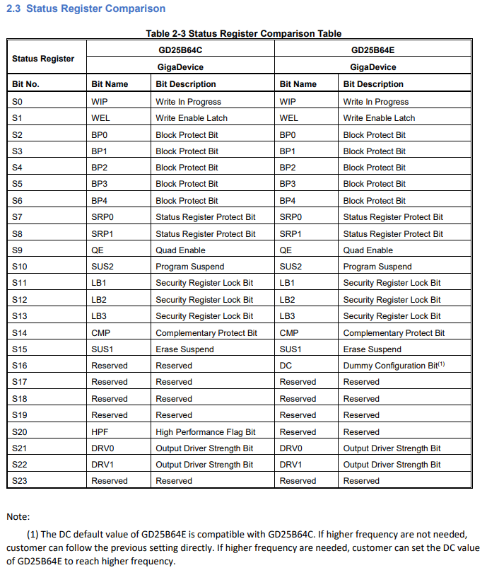
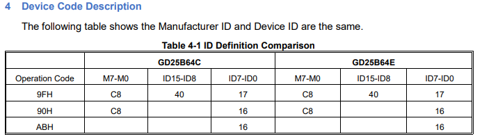
The flash device installed on the PCB is the GD25B64E, a newer revision of the GD25B64C that is listed as a compatible flash device in the application notes for the AWR2944. There are currently no suppliers that have the GD25B64C in stock, thus the change to the GD25B64E. We have also confirmed several times that we are in SOP5 mode, as well as confirming the pull-up resistor configuration for a selected 40MHz clock that is installed (CX2016DB40000D0FLJCC). Several PCs have been used trying to flash this device but the outcome is consistently the same: flash progress bar fills to 1/3 and then the flashing fails. UniFlash isn't crashing or forcing us to exit via Task Manager, it is simply failing the flash and displaying the error message. We're using the latest UniFlash version available and have tried two different mmWave SDK versions (04_06_00_01 and 04_04_01_02), so it definitely seems like it should work based on the documentation and what is in other forum posts.

We are not sure what we're missing here, there are several others across the TI forums who follow the same procedure as us yet they can successfully flash while we cannot. Can someone advise us as to what to look into next or where to go from here?

Thanks!

Harley

  • Hi Harley,

    Can you please cross-verify the specification of both the flash, GD25B64E and GD25B64C such as erase command, Quad enable bit, Flash Size in bytes, Manufacture and Device ID is everything same or is there any variation present?

    BR,

    Animesh Anand

  • Hi Animesh,

    I have a comparison document directly from the manufacturer of both devices, GigaDevice, that directly compares the operating conditions, performance, status registers, and commands. I've attached the tables to this post for your reference. The only discrepancies I see between the two devices are the following:

    • Status Register Comparison
      • S16
        • GD25B64C: Reserved bit
        • GD25B64E: Dummy Configuration bit
      • S20
        • GD25B64C: High Performance Flag bit
        • GD25B64E: Reserved bit
    • Command Comparison
      • Quad I/O Word Fast Read
        • GD25B64C: E7h
        • GD25B64E: NA
      • Fast Page Program
        • GD25B64C: F2h
        • GD25B64E: NA
      • Read Manufacture/Device ID by Dual I/O
        • GD25B64C: 92h
        • GD25B64E: NA
      • Read Manufacture/Device ID by Quad I/O
        • GD25B64C: 94h
        • GD25B64E: NA
      • High Performance Mode
        • GD25B64C: A3h
        • GD25B64E: NA

    The QE bit is active in the GD25B64E and cannot be changed. Both devices have a flash size of 64Mb and both have the same device ID and manufacturer ID.

    ID.     

  • Hi Harley,

    Can you check the value of Quad enable type value and reset type value?

    And further the data provided by, read command value is different as well as for write command. Can you also check the same?

  • Hi ,

    GD25B64C is already supported and tested flash part with AWR2944 but I understand that due to stock unavailability you need to use GD25B64E.

    And in your comparison list, I see lot of register difference. So effectively you need to port flash driver for GD25B64E part.

    Flash driver is part of mmWave MCU Plus SDK installation

    In this driver you need to have all the required register mapping wrt your flash part.

    .

    Regards,

    Jitendra

  • Hi Harley, Justin, Ramesh

    As you mentioned in the mail that you are unsure that our flash writer is loaded on to the RAM. Can you do certain modification in SBL_UART_UNIFLASH.tiimage, just add the loop_forever function that is already defined in the application and rebuild the application and send it using uart. Then what you can do is go to CCS and the load symbol of SBL_UART_UNIFLASH.tiimage. If the symbols are getting loaded that means your code is getting loaded into RAM. Further what you can do is you can check the R5_ROM_ECLIPSE register to confirm the same. It has the value 111 for bit 2 to 0 then it confirms that your code is already loaded.

    BR,

    Animesh Anand