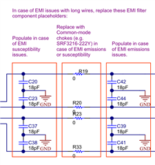
Tool/software:
Hello,
we are currently developing a device, which emits light. To ensure that the light can't be directly emitted to the eyes, we wan't to use the FDC2212 to detect if something is covering the light source. To achieve that, the light source have to be placed in the middle of the sensor.
For example like in the image below. The outer light green ring would be the sensor and connected from the back.
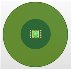 .
.
Here a some addition Information, if needed:
- On top of the light/sensor comes a few millimeters of acrylic and a 5mm silicon pillow.
- A galvanic isolated power supply is used.
- It has to withstand an medical grade EMI exam (80MHz - 2,7GHz @ 10V/m and 385MHz - 5,8Ghz @ 9V/m - 28 V/m )
1. Is a setup like this possible? Would it help to split the sensor areas into two rectangles?
The driver for the led has no fixed frequency, but a maximum switching frequency of 1MHz. There are already filters before the led and the current ripple is very small.
2. What is the preferred way to route the coil? In the image above I used a solid plane. Is there a benefit of using multiple small paths like in the image below?
3. Since the frequencies during the EMI immunity Exam are much higher, is the probability that the device is affected low? Or are there are points to consider (just regarding this sensor)?
Best Regards,
Daniel