This thread has been locked.

If you have a related question, please click the "Ask a related question" button in the top right corner. The newly created question will be automatically linked to this question.

AWR1843: How does the data got by DCA1000 EVM is stored for 2Tx, 3Tx usage

Part Number: AWR1843

Tool/software:

The document MmwaveRadarDeviceADCRawDataCapture.pdf (ti.com) shows how raw data captured can be interpreted.

I am using DCA1000 with AWR1843 to get complex raw data from 4Rx and 2Tx in TDM-MIMO like this
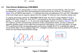
.It is told AWR1843 stores that the data like xWR16xx. So MmwaveRadarDeviceADCRawDataCapture.pdf (ti.com) shows that the complex data captured looks in non-interleaved format like below figure, where data received by each receiver is in the order of the receiver, beginning with the lowest number receiver and ending with the highest number receiver.  If there is a total of M number of chirps, the data is stored beginning with first chirp and ending with the Mth chirp.
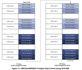
  

The document did not provide how to know that which chirp corresponds to which Tx.

My question is how can I identify which chirp data corresponds to Tx0, which chirp data corresponds to Tx1. Also, if I use 3Tx, then how to know where the data received by which chirp came from which Tx.

  • Hi Palguna,

    My question is how can I identify which chirp data corresponds to Tx0, which chirp data corresponds to Tx1.

    Tx antenna is enabled according to what you have configured in the chirp config.

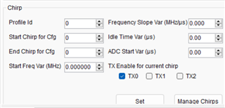
    I am assuming that you are using mmWave Studio to capture the ADC data. When you configure the chirps, you should select which Tx should be enabled for the current chirp.

    Regards,

    Samhitha

  • You mean the first four chirps corresponds to 4 Rx, Tx0,

                           next four chirps corresponds to 4 Rx, Tx1,

                          next four chirps corresponds to 4 Rx, Tx0,

    (or) 

                           first chirp corresponds to Rx0, Tx0,

                           next chirp corresponds to Rx0, Tx1,

                          next chirp corresponds to Rx1, Tx0,

                           next chirp corresponds to Rx1, Tx1,

                          next chirp corresponds to Rx2, Tx0,

                           next chirp corresponds to Rx2, Tx1,

                          next chirp corresponds to Rx3, Tx0,

                           next chirp corresponds to Rx3, Tx1,

                          next chirp corresponds to Rx0, Tx0,

    which of these for my case? 

    i did like this for the TDM-MIMO as shown in the question

    (in chirp config:)

    chirp start index, end index = 0, 0 for Tx0,

    chirp start index, end index = 1, 1 for Tx1,

    (in frame config:)

    start chirp Tx =0, end chirp Tx =1

  • Hi Palguna,

    I think that you are referring to the ADC data. For the 1st chirp, only Tx0 is enabled and for the 2nd chirp, Tx1 is enabled. In non-interleaved mode, you will receive the ADC data of 1st chirp and 4Rx (in the order of Rx0, Rx1, Rx2 and Rx3) followed by the ADC data of 2nd chirp. 

    Regards,

    Samhitha

  • Thank you. So it is 

                            first four chirps corresponds to 4 Rx, Tx0,

                           next four chirps corresponds to 4 Rx, Tx1,

                          next four chirps corresponds to 4 Rx, Tx0,

    .

    .

    .

    .