This thread has been locked.

If you have a related question, please click the "Ask a related question" button in the top right corner. The newly created question will be automatically linked to this question.

AWR1843: How to perform DoA on Range doppler data of Awr1843

Part Number: AWR1843


Tool/software:

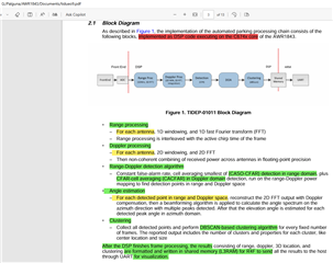
Hi. I am using DCA1000 to get the raw data of AWR1843. The signal processing chain of AWr1843 is shown below.

I am able to get the RD plot as shown in the postProc of mmWave studio and applied CFAR on it to get the detected object range and doppler bins.

Like range-FFT and doppler-FFT, I performed angle-FFT in angle domain (i.e.by taking the samples of each Rx corresponding to the (range bin, doppler bin) of the detected object and perfumed FFT on it).

But I am getting different angle than what I can calculate from the XY plot (detection and angle estimation results plot) shown in the radarStudio PostProcessing window that appears after clicking the mmWave studio. I thought may be this is not the way angle detection is performed. 

Then I looked at the above figure. The signal processing chain shown in the above figure is telling that beamforming is used for angle estimation. So looked at "C:\ti\mmwave_studio_02_01_01_00\mmWaveStudio\MatlabExamples\4chip_cascade_MIMO_example\modules\DOA\@DOACascade\DOA_beamformingFFT_2D.m" for knowing how to calculate the angle.

But the code is asking terms like "2D matrix providing antenna coordinates" which I do not know.

So my question is

1) How to obtain the angle corresponding to the detected objects in CFAR.

2) AWR1843 is a single chip device. So, Can I follow the code in "DOA_beamformingFFT_2D.m" which is basically provided for cascade devices. 

3) Where can I find this "2D matrix providing antenna coordinates" for AWR1843 device.

  • Hi Palguna,

    Please find my comments below:

    1. You can see the angle estimation algorithm that we use in the OOB demo for the AWR1843 for this purpose.
    2. We cannot perform beamforming the way do with the cascade system due to constraints such as phase shifter and number of available virtual antenna channels. You can instead refer to the AWR1843 MRR Beam steering application in the Radar Toolbox (part of TI Resource explorer) in the ADAS folder.
    3. Following 2), this might not be required for now.

    Regards,

    Kaushik

  • 1) Could you please specify where exactly I can find this "angle estimation algorithm". I saw OOB demo folder in mmWave SDK installation folder. But can't find any.

    2)Is this MRR Beamsteering Users Guide (ti.com) the link of AWR1843 MRR Beam steering application in the Radar Toolbox (part of TI Resource explorer) in the ADAS folder.(avilable under example projects of Corner Radar Overview (ti.com))? Even this doesn't describe any procedure to find the angle from the raw data obtained using AWR1843. This link description is saying

    • This lab exercise demonstrates the use of the 6-bit phase shifter on AWR-1843 mmWave sensor to steer the beam at programmable angles with ranges up to 150m.

     I am looking for a procedure to find the angle of the detected object from the raw data after applying CFAR on it, not steer the beam in required angle.

  • Hi Palguna,

    Thank you for your patience. Please find my responses as below:

    1. You can find it in the folder mmwave_sdk_03_06_00_00-LTS\packages\ti\datapath\dpc\dpu\aoaproc/src
    2. Yes. This MRR Beamsteering example application is a part of the TI Resource explorer available through the radar toolbox.
      1. You can look for the function 
        aziEleProcessing() to understand how the angle processing is done here. This can be found in the following file:
        radar_toolbox_<ver>\source\ti\examples\ADAS\mrr_beamsteering\src\1843\dss\dss_data_path.c

    Regards,

    Kaushik