Other Parts Discussed in Thread: PGA460, BOOSTXL-PGA460
Tool/software:
Dear Madam/Sir,
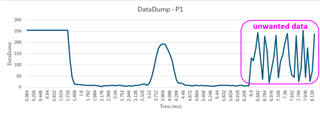
I am seeking for help to get rid of the unwanted data from DataDump as highlighted in yellow below <130,118,172,244,144,35,227,163,22,80,138,231,43,114,147,197,240,102,56,45,229,25,85,253,45,176,26,75,237>.
I used MCU with Arm Core M4 to write the code, use UART1 for communication (baud rate: 9600, no parity bit, 8 data bits, 2 stop bits) with PGA460-Q1, and use another UART2 to print the debug data.
I followed the source code from www.ti.com/lit/zip/slac741
1) initThresholds - Do not find issue. I also printed the register data from 0x0~0x2b, 0x40~0x4d, 0x5f~0x7f for verification after PGA460 Initialization and configuration.
2) runDiagnostics - Do not find issue.
3.1) runEchoDataDump - Unwanted data <130,118,172,244,144,35,227,163,22,80,138,231,43,114,147,197,240,102,56,45,229,25,85,253,45,176,26,75,237> at the end of the DataDump has occurred. It seems not to be noise because I have verified the checksum from DataDump[0] to DataDump[128] and it is as same as that in DataDump[129] which is 221.
3.2) pullEchoDataDump
4.1)ultrasonicCmd - Do not find issue.
4.2)pullUltrasonicMeasResult - Do not find issue. The object distance of about 0.6 meters is correct.
Using another UART2 to print the debug data as follows:
1.initThresholds-buf16:55,10,88,88,88,88,88,88,84,21,8,42,10,80,80,80,80,0,88,88,88,88,88,88,84,21,8,42,10,80,80,80,80,0,
Verify register data from address 0x0 ~ 0x2b: 0,0,0,0,0,0,0,0,0,0,0,0,0,0,0,0,0,0,0,0,88,88,88,82,8,20,80,60,8c,a0,10,10,55,55,19,33,fe,7c,f,0,0,9,9,62,
Verify register data from address 0x40 ~ 0x4d: 0,8b,4d,f3,72,6,47,7c,d3,1,97,0,80,0,
Verify register data from address 0x5f ~ 0x7f: 88,88,88,88,88,88,84,21,8,42,10,80,80,80,80,0,88,88,88,88,88,88,84,21,8,42,10,80,80,80,80,0,28,
2.1.runDiagnostics-diagMeaResult:40,40,40,40,40,40,40,40,
System Diagnostics - Frequency (kHz): 60.606061
System Diagnostics - Decay Period (us): 1056.000000
2.2.runDiagnostics-tempNoiseMeasResult:40,77,7,41,0,0,
System Diagnostics - Die Temperature (C): 36.666667
2.2.runDiagnostics-tempNoiseMeasResult:41,77,7,40,0,0,
System Diagnostics - Noise Level: 7.000000
Retrieving echo data dump profile. Wait...
4.2.pullEchoDataDumpBulk
64,255,255,255,255,255,255,255,255,255,255,255,255,255,255,255,255,255,255,255,119,45,15,12,12,11,11,9,8,8,8,8,7,5,4,7,7,7,8,8,7,8,8,7,5,6,7,5,7,8,9,11,14,15,9,18,41,85,137,172,190,194,191,170,150,122,77,33,18,19,14,9,8,8,6,8,8,7,9,7,7,7,6,6,6,7,8,8,8,9,8,7,8,6,7,9,9,5,7,7,130,118,172,244,144,35,227,163,22,80,138,231,43,114,147,197,240,102,56,45,229,25,85,253,45,176,26,75,237,221,
Verify checksum: 221
4.3.pullEchoDataDumpBulk-bulkString:255,255,255,255,255,255,255,255,255,255,255,255,255,255,255,255,255,255,255,119,45,15,12,12,11,11,9,8,8,8,8,7,5,4,7,7,7,8,8,7,8,8,7,5,6,7,5,7,8,9,11,14,15,9,18,41,85,137,172,190,194,191,170,150,122,77,33,18,19,14,9,8,8,6,8,8,7,9,7,7,7,6,6,6,7,8,8,8,9,8,7,8,6,7,9,9,5,7,7,130,118,172,244,144,35,227,163,22,80,138,231,43,114,147,197,240,102,56,45,229,25,85,253,45,176,26,75,237,
6.1.ultraMeasResult - obj1:41,d,b1,61,c4,0,0,0,0,0,0,0,0,0,0,0,0,0,0,0,0,0,0,0,0,0,0,0,0,0,0,0,0,0,0,0,0,
objReturn: 0.600936
P1 Obj1 Distance (m): 0.600936
6.1.ultraMeasResult - obj1:41,d,bc,5c,b9,0,0,0,0,0,0,0,0,0,0,0,0,0,0,0,0,0,0,0,0,0,0,0,0,0,0,0,0,0,0,0,0,
objReturn: 0.602994
P1 Obj1 Distance (m): 0.602994
6.1.ultraMeasResult - obj1:41,d,b5,5d,be,0,0,0,0,0,0,0,0,0,0,0,0,0,0,0,0,0,0,0,0,0,0,0,0,0,0,0,0,0,0,0,0,
objReturn: 0.601622
P1 Obj1 Distance (m): 0.601622
Could you please help?
Thank you.
Regards,
BL


