This thread has been locked.

If you have a related question, please click the "Ask a related question" button in the top right corner. The newly created question will be automatically linked to this question.

DCA1000EVM: Inquiry about Inter-Frame Time in AWR1642BOOST FMCW Radar

Part Number: DCA1000EVM
Other Parts Discussed in Thread: AWR1642BOOST,

Tool/software:

Dear Texas Instruments Support Team,

Hello,

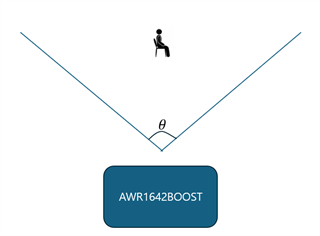
I am currently working with the AWR1642BOOST FMCW radar for vital sign measurement and have a question regarding the timing parameters of the radar signals.

I understand that the idle time refers to the duration between chirp signals, and a series of chirp signals constitutes a frame. However, I am unclear about the specific term and duration for the time between consecutive frames. Could you please provide information on what this interval is called and how it is determined in the context of the AWR1642BOOST radar?

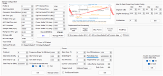
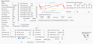
Additionally, I'm using DCA1000EVM and mmWave Studio. I have attached an image of the radar configuration parameters. Could you advise on which parameter(s) I need to adjust in order to modify the time between frames?

Thank you for your assistance.

Best regards,

Kim

  • Hello,

    The idle time between frames is usually called as Inter frame idle time.

    This can be configured indirectly by adjusting the Periodicity in the "Frame" dialog box which is the Frame periodicity. For more details on mmWave studio tool, refer mmWave studio user available at studio_location\docs\mmwave_studio_user_guide.pdf.

    Thanks.

  • Hi,

    Thank you for your kind reply.

    I understood what you said.

    I'm sorry, but I have a question.

    Based on the parameters in the attached image, the calculation [Idle Time(100us) + Ramp End Time(60us)] x No of Chirp Loops(128) results in a duration of 20.48ms. If I set the Periodicity to 40ms, there is a remaining time of 40ms - 20.48ms = 19.52ms in a Frame.

    My question is: Does this remaining 19.52ms represent a period where nothing happens before the next frame starts, or is there any other process taking place during this time?

    Thank you for your assistance.

    Best regards,

    Kim.

  • Additionally, this is a different topic, but I would like to ask:

    I have another question regarding the maximum operational angle (theta) of the AWR1642BOOST device.

    • Can you please inform me of the maximum theta angle for the AWR1642BOOST device as shown in the attached experiment setup?
    • Is it possible to adjust this theta angle?

    Thank you for your assistance.

    Best regards,

    Kim.

  • Hello,

    The processing of the data collected during chirping takes place in inter-frame idle time. Always ensure that the inter-frame idle time should be greater than the processing time. 

    Thanks.

  • Hello,

    Are you referring to theta as maximum Azimuth or maximum Elevation range?

    Thanks.

  • Hello,

    I aplogize for not being more specific.

    I mean both.(maximum Azimuth and maximum Elevation range)

    Best regards,

    Kim.

  • Hello,

    The azimuth and elevation range depends on the antennas design. For reference, our AWR1642BOOST EVM antennas have the azimuth range (~150degrees) and elevation (~45 degrees) as shown in the https://www.ti.com/lit/ug/swru508c/swru508c.pdf. I have attached the snap below taken from the same user guide.

    Thanks. 

  • Thank you for your kind reply.

    Have a nice day.

    Best regards,

    Kim.