This thread has been locked.

If you have a related question, please click the "Ask a related question" button in the top right corner. The newly created question will be automatically linked to this question.

TMP61-Q1: Suggestions for Current Bias Circuit for TM61

Other Parts Discussed in Thread: TMP61-Q1, TL432LI, LM334, TMP61, TL1431, INA500

Hello E2E Community,

We are evaluating low-cost alternatives to the typical voltage divider configuration when using the TMP61-Q1 in our application. Our setup involves a cable distance of 1 meter from the sensor to the MCU board, and we anticipate potential noise issues. We plan to use RC based LPF before ADC input - R:10kOhm & C:0.1uF along with ADC Hardware oversampling of 1024 samples.

Specifically, we seek guidance on the following points:

  1. Is it feasible to use the TMP61-Q1 with a simple 10kΩ bias resistor, given the dynamic range of 1.3V to 2.1V, in an environment with 1-meter long cables?

  2. Would using components like the LM334 or TL432LI as a current source provide a more reliable and noise-immune configuration compared to the standard voltage divider approach?

  3. For soldering what is the maximum temperature the leads can sustain? Can brief temperature of 250'C brazing operation be acceptable for these sensors (as standard with RTDs)?

  4. Can we install 2 x TMP61 sensors in parallel to lower the offset voltage & then add gain of 2 to improve the dynamic range using? Is this even a feasible line of thought?

Additionally, we face extreme space constraints and prefer to minimize the use of additional components, particularly passive components.

We are also interested in low-cost current source options from TI that can help optimize the implementation of the TMP61-Q1 in our use case.

Your insights and recommendations would be highly valuable for our decision-making process and to ensure the reliability and accuracy of our temperature monitoring system.

Thank you for your support.

  • Hi Neet,

    My first question here would be: do you know what kind of noise you expect in this application? I.e. do you know any specific frequency ranges and whether it is conducted or radiated noise? We have characterized TMP61 in a BCI setup for conducted noise immunity. From this, depending on the frequency range, I would recommend implementing an RF ceramic capacitor across the thermistor for filtering. I would also recommend following best EMI layout practices such as implementing ferrites, shielding/burying your signal traces, avoiding power/GND large loops, and so on. If you need more information on EMI performance of TMP6 please let me know.

    In terms of your questions, please see my feedback below:

    1. I do not have any concerns with this configuration in terms of accuracy. What may be affected in this case would be thermal response due to the added coupling capacitance from the cabling. This RC effect will highly depend on the total capacitance and series R. However, this would be true with any other device that has a similar form-factor as TMP61 so this is not a device-specific consideration.
    2. If you expect significant series resistance from the cabling, I would recommend looking into implementing an Ibias source instead. For this, I recommend using TL1431 as described in this app note.
    3. I am assuming in this case that you are considering an oven reflow soldering process, is this correct? If so, 250°C should be ok. Please refer to the following documents for more info on this: MSL Ratings and Reflow Profiles and Recommended Soldering Profiles (Wave soldering).
    4. This would not be possible using TMP61. You should think of this device as a current-dependent voltage source. With 2 devices in parallel you would be splitting the current between them which could lead to an unkown/unexpected node voltage at the output. For signal conditioning, I would recommend looking into the following app note so that you can match the signal to your desired dynamic range. This goes against the idea of minimizing footprint size so I would also recommend considering using the Ibias circuitry mentioned above so that you could match the dynamic range of the device as much as possible to your goal.

    As a side note, I am currently working on an app note for signal conditioning requirements according to ADC specs with both Vbias and Ibias topologies. In the Ibias, I will also be describing how to design a reference current using TL1431 in detail. 

    I have reached out to a couple of FAEs to further support your inquiries as needed since there seem to be a few different projects on different topics going around in the blog. Please check your E2E direct messages.

    Best regards,

    Simon Rojas

  • Hello ,

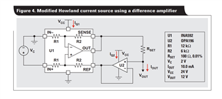
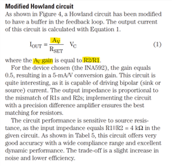
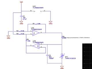
    Thank you for your detailed feedback. I agree with use of Current Bias for TMP61. I came across one of the TI's Application notes on Current Source Circuits where they have used Modified Howland Current Source. Now this being a cost sensitive use case, we found INA500 - to be within our budget & it eliminates the need for closely matched resistors as required with discrete implementation, can you suggest if we can use INA500 & create a Ibias source for the TMP61?

    With limited experience with Analog designs, we rely on your feedback & insights, they shall be significantly helpful.

    Fig 1: Modified Howland Current Source from one of TI's App Notes

    Fig 3: Note about the Modified Howland Current Source

    Fig 4: Suggested Current Source using discrete implementation in Thermistor Design Toolkit