


Other Parts Discussed in Thread: DCA1000EVM, , AWR1243
Tool/software:
Hello,
I am using the DCA1000EVM, AWR2243BOOST, and mmwave studio 3.0.0.14 to try and capture raw data. I am specifically interested in directly reading the UDP packets coming over ethernet during data capture and parsing them in real time using some custom C++ code I have written. I will set up my sensor using mmwave studio, then begin a C++ program that is searching for packets from ethernet, and then I will "trigger the frame" in mmwave studio, beginning data transmission.
Currently, I am treating the incoming packets the same way they are defined in the literature for the AWR1243 board (since I have not been able to find 2243 specific information). The methods are described in the ADC Raw Data Capture Guide code examples and images, as well as the DCA1000EVM Data Capture Card User Guide. I treat the packets as having the following structure: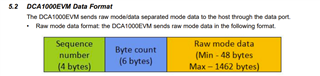
with the data itself having the structure: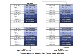
When I use this method I am able to successfully parse the sequence number and byte count from the incoming packets. I am also able to parse the packet data as shown and form my frame data. However, here is where I run into an issue. If I perform an FFT on a single chirp of data (256 complex numbers), the output looks like this: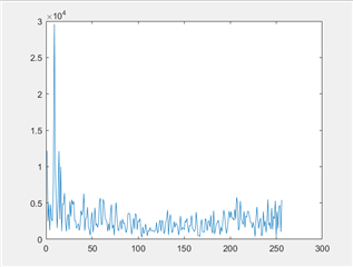
With the peak at bin 9 corresponding with my body in front of the sensor. The peak is in the correct location, so this graph is somewhat reasonable. However, if I do not use my C++ program and instead use mmwave studio for raw data capture, I get something slightly different. For example, here is an FFT taken of one chirp of data (with the same environment as the previous graph), but the data is taken from adc_data_raw_0.bin:
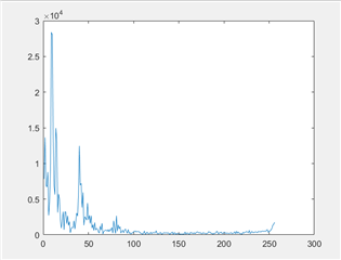
As you can see, the large peak due to my body blocking the sensor is similarly defined in both FFTs and has a similar magnitude. The smaller peak in this FFT is due to noise, it isn't important for this question. Most notably, in this FFT, the noise in the higher frequency bins is much, much lower than when I read in the data with my C++ code. The goal of this project is to measure breathing using the sensor (using the change in phase of the FFT bin where a subject is located). When I look at the phase of bin 9 (where I am located) using the mmwave studio-captured raw data, I can clearly see my breathing (this example shows four breaths):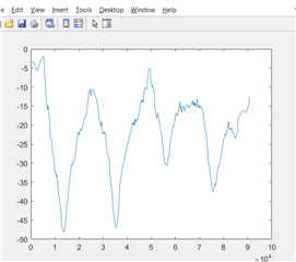
When I look at the phase of the data I collected using my program, however, the phase approaches negative infinity: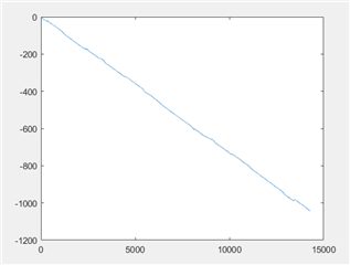
I have verified that my program is adding zeros for missed packets, and I am sure it is not dropping lots of packets (usually it drops none). I believe it may be due to how mmwavestudio reads in each integer (and perhaps I am reading them incorrectly) or due to the raw data format of the AWR2243Boost (which has no online documentation, as pointed out by another user here). However, since my FFT roughly matches what I expect to see I believe that maybe I am reading some of the data in correctly but not all of it.
I would appreciate if someone could better describe how mmwavestudio processes the incoming udp packets and places them in the raw data bin when using the AWR2243boost. Currently this is not public code and has no external documentation. Thanks!
