Tool/software:
Hi, Supporter,
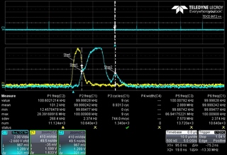
We encountered the following waveform while using the TDC7201. We are measuring in MODE 1. The Start input uses the same signal as the trigger signal (S1), while the Stop signal receives another signal to measure the rising edge (S2) and falling edge (S3) separately, with a measurement period of 100 kHz. Please see Figure 1, where the green and blue lines represent the INTBx for S2 and S3, the red line indicates the measurement reset operation period (SPI), and the yellow line represents the trigger signal (S1). At the beginning, as shown in Figure 1, the INTBx responds correctly, but occasionally it fails to go low, causing the subsequent process to not respond correctly. What could potentially cause this situation? Could you please provide us with some suggestions?
Thank you.
Another question:
According to the recommended operating conditions in section 6.3 for Mode 1, the minimum interval between two stop signals is 67 ns.
However, we found that with the NUM_STOP setting to detect two signals, the 7201 can still detect them even when the interval between the two stop signals is less than 67 ns.
Why is this?"
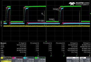
Figure1


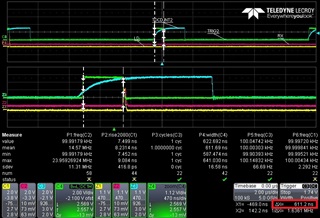 Figure2
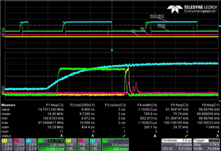 Figure3
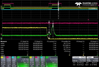 Figure 4