This thread has been locked.

If you have a related question, please click the "Ask a related question" button in the top right corner. The newly created question will be automatically linked to this question.

AWR1243BOOST: RadarDLL not Found

Part Number: AWR1243BOOST
Other Parts Discussed in Thread: AWR1243

Tool/software:

Hi 

I have installed mmwave studio 2.1.1.0 and it was working fine. 

But recently it is unable to fetch the RadarLinkDLL.dll file.

I have checked the directory for the existing of the file and i can find the file.

I tired uninstalling and reinstalling the application but still i am  facing the same issue.


[17:10:20] &&&&&&&&&&&&&&&&&&&&
[17:10:20] ***Script FAILED!***
[17:10:20] &&&&&&&&&&&&&&&&&&&&
[17:10:20] Exception message is:
[17:10:20] Unable to load DLL 'RadarLinkDLL.dll': The specified module could not be found. (Exception from HRESULT: 0x8007007E)

I have seen may of them facing the error in the forum but the suggestion did not help me.

Does DCA1000 also need to be connected to run the script to load the DLL?

 Because during my initial installation i have not connected the Board but still i was able to open the Radar Tool Box.

Hoping for your help and support

Regards 

Gopal  

  • Hi Aozer

             Thanks for your response.

              I have tried with various Microsoft Visual C++ but still stuck with same error.

             As per my understanding updating FTDI driver has no relation with opening a DLL file nor the file require Physical DCA1000 and AWR1243 connected.

    Hoping for help and support.

    Regards 

    Gopal


  • Hello,

    Ok, but did you try the method described in the thread? It has worked for other users so it may work for you. You are correct that it should not impact DLL search but it has worked for others. If you search on E2E there are several threads where this has fixed the same error.

    Regards,

    Adrian

  • Hi Aozer

         I am able to open the radar window. I have followed the steps to capture the data but when performing PostProc an Error hits on  the output window which is as follows 

    [12:10:57] ConfigureRFDCCard_Record(): UDP recvfrom failed : 10040
    [12:10:57] Configure Record :
    [12:10:57] OS error - -2

    [12:11:44] [RadarAPI]: ar1.StartFrame()
    [12:11:44] [RadarAPI]: Status: Passed
    [12:11:44] Frame start async event received!
    [12:11:45] Frame End async event received!
    [12:11:45] [RadarAPI]: Frame Ended
    [12:12:54] [RadarAPI]:
    [12:12:54] [RadarAPI]:
    [12:12:54] Start Record command : Success
    [12:12:54]
    [12:12:54] Record Process :
    [12:12:54] Timeout Error! System disconnected
    [12:12:54]
    [12:12:54] Record stop is done successfully
    [12:12:54] [RadarAPI]: ar1.StartMatlabPostProc("C:\\ti\\mmwave_studio_02_01_01_00\\mmWaveStudio\\PostProc\\adc_data.bin")
    [12:12:54] [RadarAPI]: No of files Captured: 0, Total no of frames for each device : 8
    [12:12:54] Error : The number of files captured is zero!

    I followed various threads which ask me to disable firewall. I have ping the device through cmd to which it responds.

    Regards

    Gopal

  • Hello,

    Have you properly connected to DCA1000? From your snippet it looks like DCA1000 is not properly connected via static IP.

    Please follow steps in DCA1000 training video to make sure it is properly connected.

    DCA1000 Training Video | Video | TI.com

    Regards,

    Adrian

  • Hi Aozer

    Following is my network status  configuration and ping details to 

  • Hello,

    Can you please share your full studio console log?

    Regards,

    Adrian

  • Hello 

    I have established Communication with the board. But unfortunately i am facing other error.

    [09:58:45] FPGA Version : 2.9 [Record]
    [09:58:45]
    [09:58:49] [RadarAPI]: ar1.CaptureCardConfig_StartRecord("C:\\ti\\mmwave_studio_02_01_01_00\\mmWaveStudio\\PostProc\\adc_data.bin", 1)
    [09:58:50] [RadarAPI]: Sending start_record command to DCA1000
    [09:59:20] [RadarAPI]:
    [09:59:20] Start Record command : Success
    [09:59:20]
    [09:59:20] No LVDS data
    [09:59:20]
    [09:59:20] Record stop is done successfully
    [09:59:26] [RadarAPI]: ar1.StartFrame()
    [09:59:26] MSS power up done async event received!
    [09:59:28] MSS power up done async event received!
    [09:59:30] Status: Failed, Error Type: RESP TIMEOUT
    [09:59:42] [RadarAPI]: ar1.StartMatlabPostProc("C:\\ti\\mmwave_studio_02_01_01_00\\mmWaveStudio\\PostProc\\adc_data.bin")
    [09:59:42] [RadarAPI]: No of files Captured: 1, Total no of frames for each device : 8
    [09:59:42] [RadarAPI]: Error:
    [09:59:42]
    [09:59:42] ... MWMCR::EvaluateFunction error ...
    [09:59:42] 22-Aug-2024 09:59:42: Incorrect number of samples. We expect 262144. However, we got 120832.,1,
    [09:59:42] Error in => process_adc_data.m at line 79.
    [09:59:42]
    [09:59:42] ... Matlab M-code Stack Trace ...
    [09:59:42] at
    [09:59:42] file C:\Users\tg-gr\AppData\Local\Temp\tg-gr\mcrCache8.5.1\Matlab0\Logging\log_status.m, name log_status, line 32.
    [09:59:42] at
    [09:59:42] file C:\Users\tg-gr\AppData\Local\Temp\tg-gr\mcrCache8.5.1\Matlab0\Processing_functions\read_adc_data.m, name read_adc_data_12xx, line 380.
    [09:59:42] at
    [09:59:42] file C:\Users\tg-gr\AppData\Local\Temp\tg-gr\mcrCache8.5.1\Matlab0\Processing_functions\read_adc_data.m, name read_adc_data, line 31.
    [09:59:42] at
    [09:59:42] file C:\Users\tg-gr\AppData\Local\Temp\tg-gr\mcrCache8.5.1\Matlab0\MatlabPostPr\process_adc_data.m, name process_adc_data, line 79.
    [09:59:42]
    [09:59:42]
    [09:59:42] Trace:
    [09:59:42] at MathWorks.MATLAB.NET.Utility.MWMCR.EvaluateFunction(String functionName, Int32 numArgsOut, Int32 numArgsIn, MWArray[] argsIn)
    [09:59:42] at MathWorks.MATLAB.NET.Utility.MWMCR.EvaluateFunction(Int32 numArgsOut, String functionName, MWArray[] argsIn)
    [09:59:42] at MatlabPostProcGui.MatlabPostProcGUIClass.process_adc_data(MWArray adc_file_name, MWArray force_cont_stream_mode)
    [09:59:42] at AR1xController.frmAR1Main.iStartMtlabPostProc()

    Regards

    Gopal

  • Hello,

    Please share your FULL console log from start to capture. What you have shared is only the capture part, I need to full log from begging to end (uart connection, load FW, SPI connect, static config, data path config, sensor config etc should all be included).

    Regards,

    Adrian

  • Hi Azoer 

    Firstly, Thanks a lot for your quick response and support 

    My board got connected and is responding as well.I stared to test the radar by placing a single object at different lengths and measuring the calculated as well as post processed data.But the results are varying a lot. To we need to calibrate the device?

                          I even tired to run the lua script "DataCaptureDemo_xWR" and as per my understanding this particular script is to check the states of configuration and prompt the messages. If i want to change few configuration which exact file i must refer. The mentioned lua script has test Source enable which i want to disable. But i could not find configuration settings in that particular file.

    I just added the line  

    ar1.DisableTestSource(0)
    ar1.FrameConfig(0, 0, 8, 128, 40, 0, 0, 1)

    It works but i need to understand were exactly the entire configuration file is located .

    Regards 

    Gopal

  • Hi Azoer 

                 I was even gong through one of the document for Interpreting Binary File in MATLAB. I am able to convert the bin file to MATLAB file.

    The output file format is a 2 dimensional array [ Elements X  (ADC_Samples*chrips*frames)];

    I want to convert it into a 3 dimensional Radar Cube will it be in a format as [ ADC_Samples X Element X (Chrips*Frames) ]

    Is my understanding correct?

    Regards 

    Gopal

  • Hello,

    The entire configuration is located in the script file itself. For example, the profile configuration is defined as ar1.ProfileConfig(0, 77, 100, 6, 60, 0, 0, 0, 0, 0, 0, 29.982, 0, 256, 10000, 0, 0, 30) in the script.

    If you need to understand what a command is you can type help ar1.ProfileConfig, etc in the lua shell to understand each command.

    Full details of each radar API are defined in the interface control document located at C:\ti\mmwave_dfp_01_02_06_03\docs.

    Yes, your understanding of the array is correct.

    Regards,

    Adrian

  • Hi Adrian

              Thanks for the conformation. 

    My board got connected and is responding as well. I started to test the radar by placing a single object at different lengths and measuring the calculated as well as post processed data. But the results are varying a lot. To we need to calibrate the device?


    Is their any documents i need to refer ahead of testing and parametrization of the device.

    Regards

    Gopal

  • Hello,

    For room temperature tests you should be fine without runtime calibrations. What is it that you consider a lot of variation?

    For calibrations you need to refer to the interface control document (ICD) located at C:\ti\mmwave_dfp_01_02_06_03\docs.

    Regards,

    Adrian

  • Hi Adrian 

          Thanks for the information. I have an other observation when i am trying to run the autoscript in which i have disabled the test source. But when i run the script i see in the output window the test source is been enabled again but i can not see any Enable command in script. I have attached the snip.

    Regards 

    Gopal

  • Hi Adrian 

           I have performed some test using the radar.

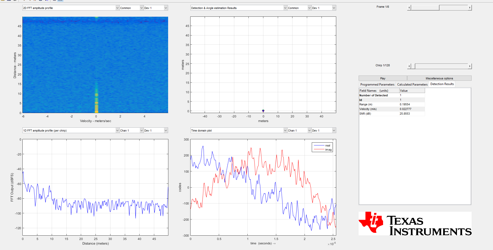
    Test01.JPG were an object is placed at 8cm.Test_001.JPG is the snap shot of the result in mmwave studio, the detection results shows 0.19m(19 cm). But, the 2DFFT Plot is quite different.


    Test02.JPG were an object is placed at 40 cm.Test_002.JPG is the snap shot of the result in mmwave studio, the detection results shows 0.58m(58 cm). But, the 2DFFT Plot is quite different.

    Regards 

    Gopal

  • Hello,

    I suggest you review the below app note to understand different radar parameters and how they impact performance.

    https://www.ti.com/lit/an/swra553a/swra553a.pdf

    If you are seeing large errors in range detection you may need to look at how you are setting the range resolution. If you want to detect close objects with fine range you need to configure the device to maximize your range resolution. You can also look at the sensing estimator which can help you setup a chirp configuration for your desired use case.

    https://dev.ti.com/gallery/view/mmwave/mmWaveSensingEstimator/ver/2.4.0/

    Regards,

    Adrian  

  • Hi Adrian 

       I am referring the pdf for the calculations. I even made an Excel which calculates these things.

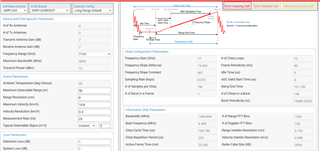
        I have feed the data as per your suggestion in mmWave Sensing Estimator and calculated back Max Range, Range Resolution ,Max Velocity and Velocity Resolution.

    As per the observation the values of Max Range and Range Resolution is correct but value differ in Max Velocity and Velocity Resolution. 

    Can you please have a look and let me know the error.

    Apart from that if i try to fill the values which i have obtained from mmWave sensing estimator into mmwave studio.

    mmWave studio does not accept Sample rate less that 200. And pops out the following error message.

    Regards 

    Gopal

  • Hello,

    For 12xx the minimum valid sampling rate is 2Msps.

    For sensing estimator computations, I will loop in the software team.

    Regards,

    Adrian

  • Hi Adrian 

                 It would be great if you can loop the team and help me with the configuration of AWR12xx ASAP.

    Regards 

    Gopal

  • Yes, this has already be reassigned to the software team. They should respond soon.

    Regards,

    Adrian

  • HI,

    Can you please start a new thread since there have been many questions already answered on this thread?

    Thank you

    Cesar