This thread has been locked.

If you have a related question, please click the "Ask a related question" button in the top right corner. The newly created question will be automatically linked to this question.

LDC5072-Q1: Signal jumps around zero levels

Part Number: LDC5072-Q1

Tool/software:

One more issue. 

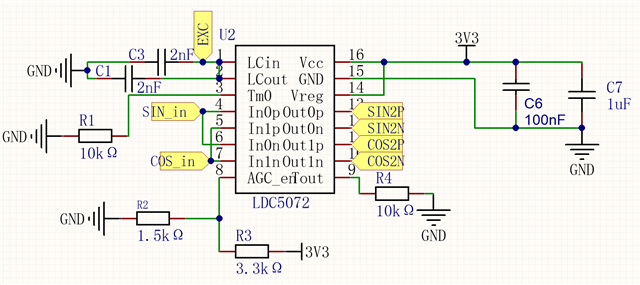
 Lexc = 1.87 uH, Rexc = 1.72 Ohm, Lin = 0.615 nH, Rin = 1.96 Ohm. C1 = C2 = 1.98 nF. Fexc = ~4.05 MHz

Vcc = 3.3 V. Vagc = 1.031 V, Gain = 2.34

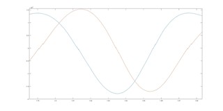
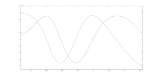
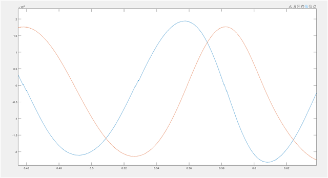
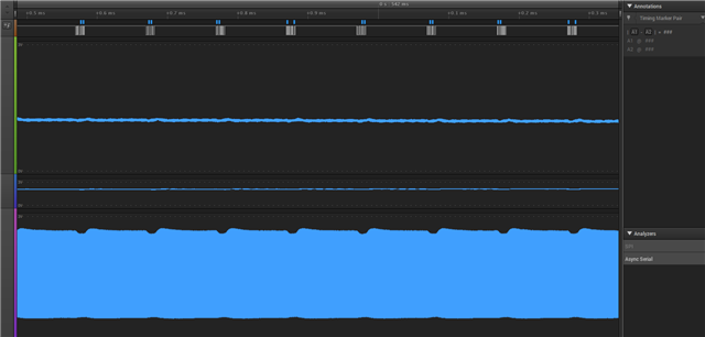
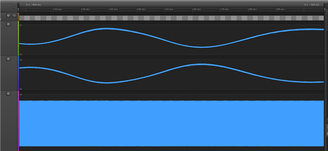
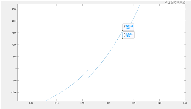
Observed signal jumps around zero levels. Tested on LDC5072 and LDC5071.

Same sensor on the Renesas IPS2550 is OK.

  • Kirill,

    What do your two uploaded images represent?

    Can you please provide an oscilloscope capture of the exciter signal with no target rotation?

    A schematic and layout of your circuit would also be helpful.

    Regards,
    John

  • This is output signals from differential 16 bit(oversapled from 12bit) ADC. Vadc_ref is 3.3 V.

    First image is output from LDC5072. Second one - from IPS2550. 
    Here is schematic. Layout cant send. I will make capture of the exciter tomorrow. But It was just sinus with amplitude around 3V without drops and spaces.
    Also I will make capture during moving.
    Actually this is linear sensor.  

  • Thank you Kirill.

    On your schematic, it looks like the exciter coil is connected only to the LCIN pin.
    is that correct?

    John

  • Nop. There is connection to LCout near the pin.
    I tryed to make capture of Lcout + Out0p + Our1p. And the issue become lesser. I placed 100 nF capacitors between Out0p - Out0n and Out1p - Out1n pins, and its gone.
    But on the LCout I observed pulsation of amplitude. Is this normal? I think they are related.

  • And I still don't understand what the jumps are related with. If out capacitors remove the noise, it is normal. But the presence of jumps behind the capacitors is not expected for me. Its sensor device and I can't put an expected angle(linear) inacuracy in it.

  • Kirill,

    A couple of things to try:

    1. Your schematic doesn't show any pull-up or pull-down resistors.
      Could you try adding some 5k-10k pull-up resistors from the output pins to 3.3V to see if that helps?
    2. The COUT resistors are at the high end of the recommended values. 
      Could you try some smaller values from the output pins to GND to see if that helps?

    Is there any movement of the rotating target other then it spinning? 
    Could there be some vibration or misalignment of the target while it spins?

    What are the connections of the receive coils?
    Is each receive coil connected differentially across the corresponding INxP and INxN?

    Regards,
    John

  • 1. 2. I will try.
    Nop. There are good bearings. I think play is less than 5 um and the movement is completely smooth.
    Coils are independed(and connected differentially). There may be parasitic capacitance present between IN1 and IN2 about 20 pF(need to check). Between exciter and input coils I think its less 3 pF.
    2. Why it doesn't work without Cout? Steps/jumps are greater than maximum inacuracy many times.
    And what about amplitude ripple of the exciter? Does it normal?

  • Kirill,

    Is there any ripple or noise on your 3.3V power supply?
    Do the amplitude variations in the exciter signal happen at random time intervals, or do they happen at regular intervals?
    Cout is needed for output noise reduction.

    Regards,
    John

  • Power supply is OK. There is TPS70933 with Cout  2.2 uF and 1 uF + 0.1 uF near LDC5072. Additional cunsumption about 30 mA.
    Every 100 us(first picture in the 4th post). Looks like PLL with slow feadback.

    Noise is normal. It makes resolution wider after filters. But clear steps are bad. 

  • Kirill,

    Does the exciter amplitude vary when the target is stationary or moving?
    If it is only when moving, what is the target's rotation speed and the number of pole pairs?

    We have not seen any steps on the output before, so I'm not sure of the root cause for what you are seeing.

    Regards,
    John

  • It always ripples with ~100 us period. And Out singnals(Sin and Cos) ripple synchronously. Sin/Cos ratio is stable. But near the zero level , clear steps(whyle moving) are observed(1st picture in the init post). And after I installed 100 nF capacitor to output, they(steps) are gone. 
    I think this is not expected.

    This is linear encoder. On the 1st picture real resolution y-16bit dif ADC out(from outp to outn pins), x- time in seconds. There is 1 period per 0.1 second. 

  • Tested with Cout 1nF and 10 nF. All ok. Pull-up resistors dont help.

  • Kirill,

    There needs to be some output capacitance per the data sheet recommendations.

    The capacitors provide two functions:
    1. They protect the output pins by absorbing ESD strikes.
    2. They provide stability for the output buffers.

    The pull-up/down resistors are to pull the output voltage to a HIGH/LOW state when the device faults and outputs buffers tri-state. 

    Does the period of the ripples on the exciter voltage change when the target speed varies?

    Regards,
    John

  • I found the pulsation cause. Its enabling RS485 communication... I checked twice power supply. Its OK. I didnt see pulsation on my plots, because I read ADC, send data via RS485 and it begins. RS485 lines is shielded (and doesnt affect absolutely same PCB with ILS2550)

    Here is plot with 1nF Cout on red line, and without Cout on blue.


    And capture of RS485 data line, Out1p, Out1n and LCout

  • These are the PCBs. This is 8 layers HDI. 4 layer on bottom for coils, 2 top layers - signals, 3rd layer from top is full GND shield. 

    Here is LCout on IPS2550.

  • And out signal steps are not related to LCout pulsation. Its separate issue.

  • Kirill,

    Would it be possible to share your layout?
    We use Altium for PCB layout. If you use a different tool, gerbers would be fine.

    From your plots, it looks like you may have some output offset, which we have found is related to the trace routing between the exciter and receive coils -> device pins. Grounding is also a factor. Perhaps this is a contributing factor to the output steps.

    Also, would it be possible to zoom in and show the details of the signal steps? 
    Perhaps there is more going on that a simple step discontinuity.

    Regards,

    John

  • Sorry. This device already in production(and in validation with IPS2550). This is prety standart square Exciter coil out, and two sin and cos coils inside. Sin and Cos coils have 2 periods size. Exciter - 2.5 periods. Exciter has no capacitive coupling with input coils. There is full grouning with gap to coils around 1.6-1.7 mm. Sensor size is 15 x 10 mm.

    Here is the zoom of steps. 2^15 is equal 3.3 V (in dif). So steps are about 33 mV. At the high speed they are smaller. The main problem is that they are clear without any noise. I dont understand this. It looks like IC schematic problem in PLL or peak detector(signal phase control). But why do output capacitors help?..
    So we cant use this for now. Will be waiting new revision. I think we can close topic.

  • Thanks Kirill.
    I will close the thread.

    Please feel free to re-open this thread or start a new one if you want to continue the discussion in the future.

    John