TDC1000-C2000EVM: TDC1000-C2000EVM

Part Number: TDC1000-C2000EVM
Other Parts Discussed in Thread: TDC1000, TUSS4470

Tool/software:

Hello Isaac, 

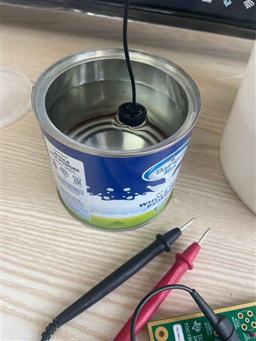
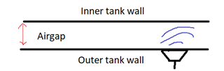
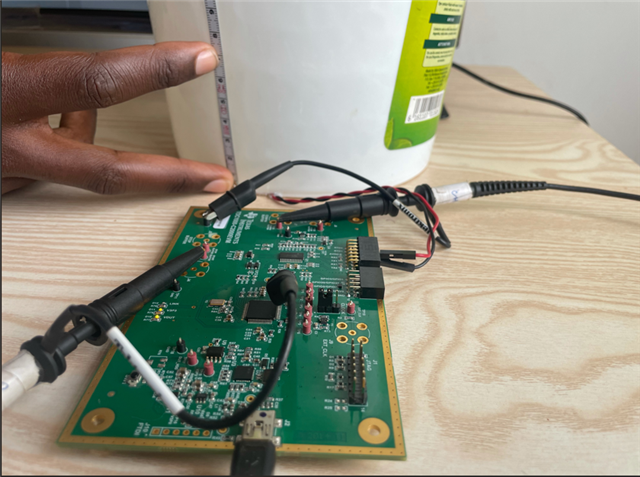
Thank you for your assistance. We mounted the transducer as you recommended and followed all the setup instructions.

The transducer we are using is PSC1.0M014085H2AD2-B0 from Jiakang electronics (TI-Partner) Ultrasonic Flow Transducers-Transducers and Sensors-Products-Zhejiang Jiakang Electronics Co., Ltd. (jkelec.com)


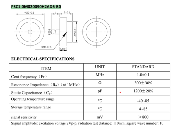
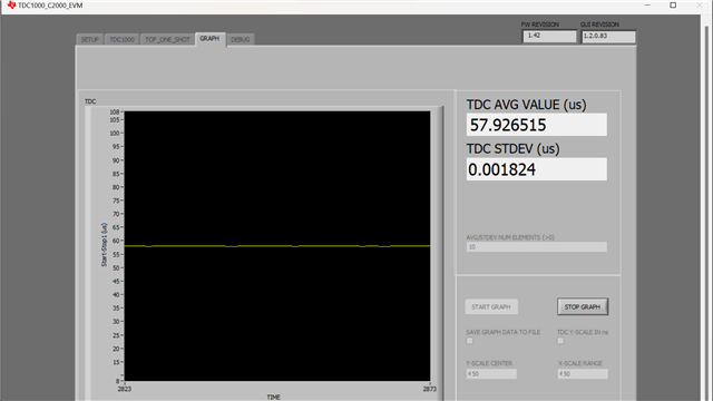
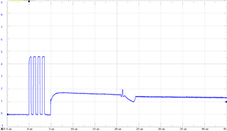
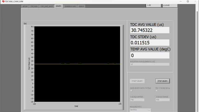
However, the GUI is showing us an incorrect yet constant TOF value which is 30.74us yet the water level is about 67mm (TOF = 90.29us).

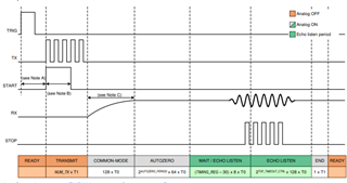
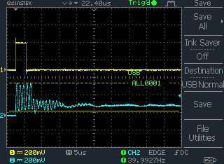
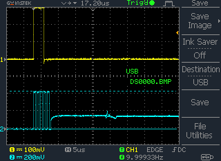
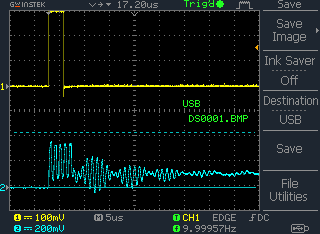
The Start Pulse is connected to channel 1 and the Compin Buffer is connected to Channel 2 of the oscilloscope in order to view the timing between the Start pulse and the Echo for the stop pulse generation.

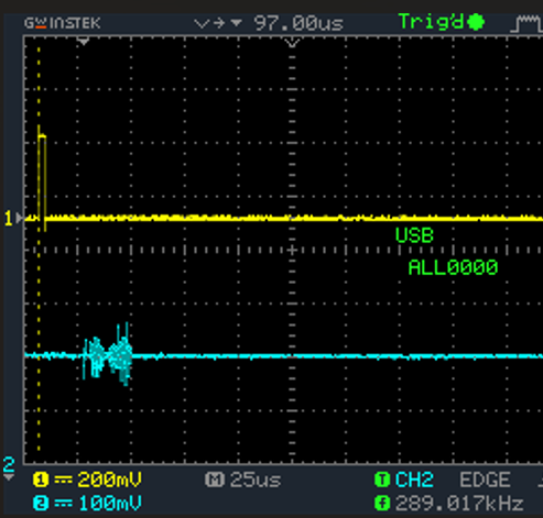
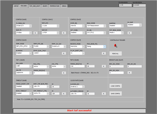
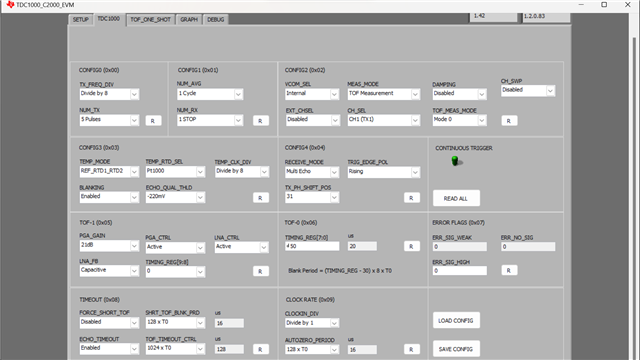
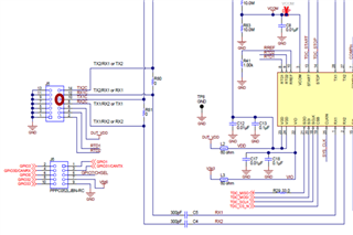
We used the following register settings 


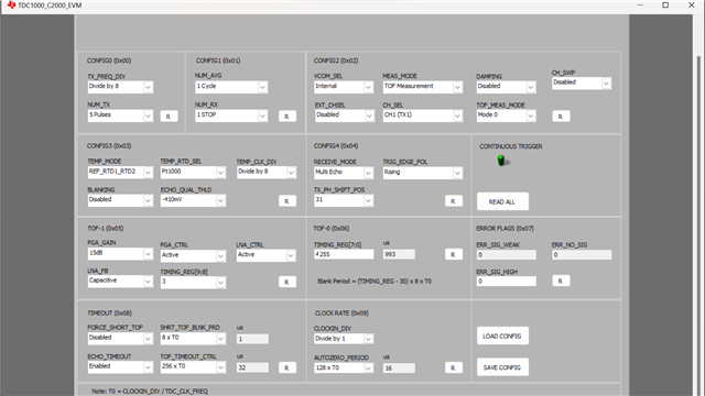
Kindly advise on the register settings we should use, and how we can get the actual TOF reading which should also vary with change in water level. 

Thank you.

  • Hello Semlayo,

    Thanks for posting to the sensors forum! I believe the issue may be your TIMING_REG settings they are currently configured to be too high for the expected signal.

    Try setting them up similar to this to see if this helps, this is a configuration I used for ~7cm of water.

    Best,

    Isaac

  • Hello Isaac,

    Thank you for assistance, we have changed the TIMING_REG settings as you recommended. However, we are still getting an incorrect TOF reading, and its not changing with water level Our results are shown in the figure below;


    The constant incorrect TOF of 30.74us has now become 57.926us. It's still far from what we must get. Below are the register settings we have used for the water level of 6.7cm 


    Looking forward to more assistance. Thank you

  • Hello Semyalo,

    Thanks for the information. Your expected ToF should be ~90us so it seems like you could possibly be triggering on some sort of noise if your liquid is set to 6.7cm.

    Can you try changing the AUTOZERO_PERIOD to a larger value? 512xT0 would ignore anything that happens for the first 80us. I included the timing diagram below but what this does is essentially shift the listening window further up to avoid triggering on some noise that could be happening earlier. Changing the TIMING_REG just increases or decreases the amount of time the comparator is active to qualify thresholds.

    This value may have to be tuned depending on what your detection range is meant to be.

    Best,

    Isaac

  • Hello Isaac,

    Thank you for your assistance thus far. We have made remarkable progress.

    When the transducer is placed directly onto the water surface, we get an accurate reading. However, when placed on the container surface externally, there is no accurate reading. It seems the TX signals are unable to penetrate the container surface.


    With reference to the datasheet, we measured Vout TX using the oscilloscope (Peak to peak amplitude) as shown below, and the result was 0.32V


    Kindly advise on how we can boost the voltage of the TX pulses to be able to penetrate container surface.

  • Hello Semyalo,

    Thanks for the information. You do need a larger voltage to penetrate through tank walls, keep in mind that metal tanks will be much harder to penetrate than plastic hence why we only recommend thin soft metals if you plan on using metallic tanks.

    As far as peak to peak voltage on the TX signal, that seems extremely low. This should be emitting at 5V from the EVM. You should be able to probe TP16 near the USB to ensure that we are getting 5V from the USB bus, you can also probe VDUT via near D10 to see what the voltage is there. If you try removing the transducer and start a measurement does it generate a ~5V signal?

    Best,

    Isaac

  • Hello Isaac,

    We have done the measurements you recommended using a digital multimeter. The results are as follows;

    TP16 V5P0           = 4.91V
    TP17 DUT_VDD   = 4.65V
    Vout TX                 = 0.016V
      
    Then, removing the transducer and starting the measurement, Vout TX results are as follows

    Vout TX = 0.033V

    Looking at the results we have, in comparison to the TDC1000 Datasheet, it looks like we have a very low voltage at the TX.
    Kindly advise on how we can boost the voltage or troubleshoot the situation at case.

    Thank you.

  • HI Semyalo,

    Isaac is out for the labor day holiday.  He should be back on Wednesday.

    Regards,

    Mekre

  • Hello Semyalo,

    Thanks for the details, to get ~5V excitation for the TX voltage you shouldn't have to do anything. The board is configured like this out voltage of the box and shouldn't require any additional configuration either in hardware or on the GUI. Can you probe with a scope like shown below to see if you can verify what the waveform looks like? Try to take a capture with and without the transducer to ensure that doesnt make a difference. Remember that the top pins on the J5 connector are your signal pins and all the connectors on the bottom are the ground pins.

    Best,

    Isaac

  • Hello Isaac,

    What TX output Peak to peak voltage do you have on the recent scope image you shared; What output TX Voltage should we be obtaining and how can we get it? 

    Thank you for your assistance this far, we have followed through to obtain the oscilloscope imagery as you recommended;

    Below is the TX waveform WITHOUT the transducer. The Peak to peak TX voltage measured using the Oscilloscope is 0.44mV as shown below. i.e Peak to peak is the measurement between the blue horizontal thick line and the blue dashed line as shown below;


    In addition, below is an image of the measured TX signal waveform WITH the transducer


    Kindly advise on how we can proceed given the two waveforms shared; TX signal WITHOUT transducer and TX signal WITH transducer.

    Thank you sir.

  • Hello Semyalo, 

    The peak to peak voltage was about 4.7V for TX , which is around what you should be getting for your TX voltage.

    As I mentioned this should be standard out of the box so there are no modifications you need to make in order to get this voltage out.

    Do you have another scope that you can use to confirm the voltages? The reason I ask this is because I assume the yellow signal is the START pulse but that also looks very low as well since this should be providing 3.3V high level signal but your capture indicates ~300mV so I am trying to make sure the scope is not attenuating the signals. The reason I believe the scope is because you were able to perform measurements with this EVM when the transducer is coupled directly with water. If the board was exciting the transducer with 0.44mV this would not be possible to get a proper TX signal or RX signal reflected back to the transducer.

    Best,

    Isaac

  • Hello Isaac,

    You are right, we changed to a different scope and readings are similar to what you have. Our peak-to-peak voltage is about 4.7V.

    Our START Pulse is also providing 3.3V high level signal.

    Question is, why we can't be able to penetrate through plastic. We have tried different kinds of thicknesses.

    Before we move to our target of a metallic container, we should at least be able to get a reading with a plastic container.

    Please advise.

    Thanks

  • Hello Semyalo,

    Sorry for the delay we are off on the weekends here in the US so we are not available to answer on those days. That is good to hear that the device is generating the appropriate voltages as expected.

    As far as not being able to detect through plastic there are two main issues that usually occur when trying to achieve this. The first one is typically mounting the transducer to the tank is not done properly. You need a very good mechanical connection between the tank and the transducer in order to have the signal penetrate properly through the tank and be able to receive the signal.

    We have this document that you can read: https://www.ti.com/lit/an/snaa266a/snaa266a.pdf

    The other issue is that the plastic tank is layered internally meaning that it has an inner wall aside from the outer tank wall. See image below, but the issue with this is that the a significant portion of the echo is reflected on the inner tank wall so the signal is not able to travel into the inner tank where the liquids are held and have enough energy to return through the inner and outer tank wall.

    Best,

    Isaac

  • Hello Isaac,

    Thanks for the help, 

    The issue must have been in register settings on the GUI. After patiently playing around with the Threshold voltage and echo zero values, we were able to get the signal go through plastic and some thin steel (about 2mm thick).

    Now the issue we have is the signal cannot penetrate through our steel LPG Cylinder (about 5mm). Of course, we are aware that the excitation/Tx Transducer voltage is too low so probably would need an HV Circuit.

    Could you please advise on how we can implement this using our EVM (TDC100-C2000)?

    Regards,

    Semyalo

  • Hello Semyalo,

    Thanks for the information that is good to hear. In order to increase the voltage of the excitation pulses you will need another circuit.

    We used to sell this EVM that was a TX boost for excitation pulses up to 30V: https://www.ti.com/lit/ug/sniu026a/sniu026a.pdf

    Unfortunately, this is no longer available for purchase but the schematics are available in the users guide. If you decide to create something similar to this you just need to ensure that the circuit you create can drive at the proper excitation frequency. As far as what is the necessary voltage you will need to penetrate the ultrasound waves through the thicker tank that will be something you will need to test out.

    You can also try to use our BOOSTXL-TUSS4470EVM the TUSS4470 is able to generate higher excitation pulses without the need of an external circuit and it can still operate at 1MHz.

    Best,

    Isaac